


PARTNER® Version, Installation and Reference Manual
Page 81
- Issue 1a (30 January 2010)
IP Office Essential Edition
System Component Details: Physical Ports
·
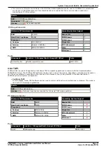
Maximum Voltage: 55V d.c.
·
On state resistance: 0.7 ohms.
·
Short circuit current: 1A.
·
Reverse circuit current capacity: 1.4A.
·
Ensure that pins 1 and 2 are always at a positive voltage with respect to pin 3.
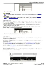
3.5mm stereo audio jack plugs are frequently sold as pre-wired sealed modules. It may be necessary to use a multi-
meter to determine the wiring connections from an available plug. Typically 3 (common to both relays) is the cable
screen.
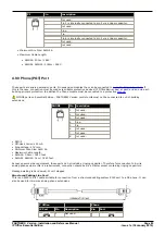
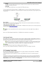
4.9.7 LAN Port
The IP Office control unit has 2 RJ45 Ethernet ports, marked as LAN and WAN. These form a full-duplex managed layer-3
switch. Within the IP Office configuration, the physical LAN port is LAN1, the physical WAN port is designated LAN2 but
should not be used.
The LAN port LEDs indicate as follows:
·
Green: On = connected, Flashing = Activity.
·
Yellow: On = 100Mbps, Off = 10Mbps.
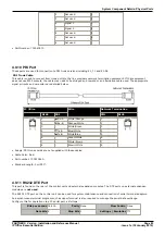
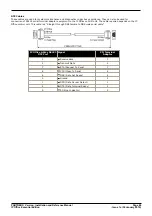
LAN Cables
These are CAT5 UTP cables for connection of various IP devices within the IP Office system.
IP Office
LAN
Pin
MDIX
(Normal)
MDI
(Crossover)
Wire
Standard/
Interconnect
Crossover
1
Rx-A.
Tx-A.
White/Orange
1
3
2
Rx-B.
Tx-B.
Orange/White
2
6
3
Tx-A.
Rx-A.
White/Green
3
1
4
Not used.
Not used.
Blue/White
4
4
5
Not used.
Not used.
White/Blue
5
5
6
Tx-B.
Rx-B.
Green/White
6
2
7
Not used.
Not used.
White/Brown
7
7
8
Not used.
Not used.
Brown/White
8
8
·
Part number:
·
LAN Cable - GREY: 700213481.
Standard straight LAN cable.
·
LAN Crossover Cable - Black: 700213473.
LAN crossover cable.
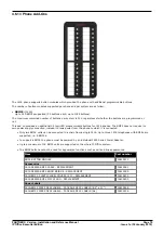
4.9.8 PF Port
These ports are analog extension ports that can be used in conjunction with analog loop-start trunks during power failure
to the IP Office system. There are a number of options to connect analog extension ports to analog trunks during power
failure. In all cases these only work with loop-start analog trunks. Any phones connected to these ports should be clearly
labeled as power fail extensions in accordance with the appropriate national and local regulatory requirements.
When an IP Office 500Analog Phone 8 base card is fitted with an IP Office 500Analog Trunk daughter card, during power
failure extension port 8 is connected to analog trunk port 12. The same applies to the IP Office 500ATM Combination card
and the IP Office 500
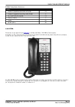
ETR6
base card.
Any phones connected to these ports should be clearly labeled as power fail extensions in accordance with the
appropriate national and local regulatory requirements.