


PARTNER® Version, Installation and Reference Manual
Page 73
- Issue 1a (30 January 2010)
IP Office Essential Edition
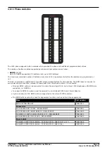
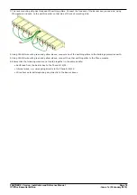
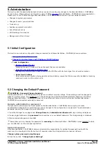
System Component Details: Out of Building Telephone Installations (COPY)
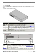
Main Building
Barrier Box
Secondary Building
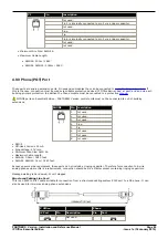
·
RJ11: Connect to PHONE (POT) port on the
Phone module using cable supplied with the
barrier box.
·
RJ45: Connect to the secondary building
barrier box via primary protection in both
buildings.
·
RJ11: Connect to analog phone.
Cable not supplied.
·
RJ45: From main building via
primary protection in both buildings.
·
Center Screw: Connect to main building
protective ground (or ground terminal of
Barrier Box Rack Mounting Kit). Use 18AWG
(minimum) wire with a green and yellow
sleeve.
·
Right-Hand Screw: Connect to ground point
on Phone module using ground cable supplied
with barrier box.
·
Center Screw: Connect to main
building protective ground. Use
18AWG (minimum) wire with a green
and yellow sleeve.
·
Right-Hand Screw: Not used.
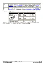
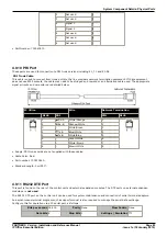
Wires from external telephone going directly to the barrier boxes must be kept apart, that is not routed in the same
bundle:
IP Office Barrier Boxes
Part number
IP Office 500 Phone Barrier Box (81V)
Use with Phone V1 module. Includes an RJ45 to RJ11 cable and a
functional earth lead.
700293897
IP Office 500 Phone Barrier Box V2 (101V)
Use with Phone V2 module. Includes an RJ45 to RJ11 cable and a
functional earth lead.
700385495
Barrier Box Rack Mounting Kit
700293905
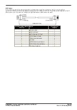
4.7.3 Rack Mounting Barrier Boxes
Where more than 3 Phone Barrier Boxes are used they must be rack mounted. The Barrier Box Rack Mounting Kit (Part
number 700293905) supports up to 8 Phone Barrier Boxes.
1. Unscrew the two screws arranged diagonally at the front of each barrier box and use these same screws to reattach
the barrier box to the rack mounting strip.
2. Each barrier box is supplied with a solid green ground wire connected to its functional ground screw. Remove and
discard this wire. Connect a green/yellow ground wire to the protective earth screw in the center of the Point on the
back of the Barrier Box.