


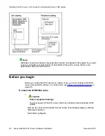


Refer to the Optivity Telephony Manager documentation for information about the Optivity
Telephony Manager application, its requirements, and how to install it.
Communication Server 1000 documentation
If you need to refer to the following Communication Server 1000 technical documents, they
are stored on the Customer Documentation Library CD-ROM (NTLH80BA), provided with your
Communication Server 1000 system:
• Communication Server 1000 Planning and Installation Guide
Note:
This guide is also provided in printed format with your Communication Server 1000
system.
• Communication Server 1000 Input/Output X21 Administration
• Communication Server 1000 Input/Output X21 Maintenance
You can search the entire suite of documentation online, or you can print part or all of a guide.
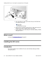
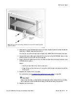
Removing the Media Gateway or Media Gateway Expansion
cover
Introduction
To access the interior of the Media Gateway or Media Gateway Expansion, you must remove
the front bezel and inside front cover plate.
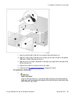
To remove the front bezel and inside front cover plate
1.
Warning:
Risk of eye injury
Avaya recommends that you operate the Media Gateway and Media Gateway
Expansion with their front bezels installed. When the blue LEDs inside these units
are lit, they are very bright.
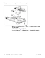
Installing the 201i server in the Avaya Communication Server 1000 system
80 Avaya CallPilot
®
201i Server Hardware Installation
December 2010