


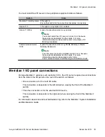


Meridian 1 I/O panel connections
On the Meridian 1, the 201i server requires two connections from the slots to the I/O panel on
the rear of the switch, as follows:
• One connection is for the multi I/O cable.
This connection corresponds to the left slot (when viewing the front of the Meridian 1
switch).
• The other connection is for the external SCSI device.
This connection corresponds to the right slot (when viewing the front of the Meridian 1
switch).
For information about slot and rear bulkhead wiring, refer to the Meridian 1 System Installation
and Maintenance Guide
Secondary backplane connector
The secondary backplane (DS30X) connector on the 201i server connects the server to the
second slot on the shelf, thereby providing access to the voice channels provided by that slot.
Caution:
Risk of equipment damage
The 201i server is shipped ready for installation into an Option 11C switch. Before you install
the 201i server in a larger Meridian 1 switch (for example, Option 51C), you must move the
secondary backplane (DS30X) connector to the correct position.
Important:
A yellow warning label over the top lock latch on the 201i server prevents you from securing
the 201i server in a slot. This label serves as a reminder to move the secondary backplane
connector to the Meridian 1 position, if required, before installing the 201i server into the slot.
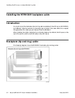
Backplane (tip and ring) cable
The backplane (tip and ring) cable supplied with the 201i server (NTRH3501) provides
100Base-T Ethernet operation for the Avaya server subnet. This cable offers more network
throughput than the cable that is already installed on the Meridian 1.
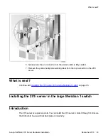
Installing the 201i server in a large Meridian 1 system
38 Avaya CallPilot
®
201i Server Hardware Installation
December 2010