


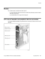


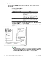


The switch connector is a 50-pin amphenol connector.
The RJ-45 CLAN and ELAN connectors support the following network protocols:
• ELAN: 10Base-T Ethernet
• CLAN: 10/100Base-T Ethernet
The modem connector is a 9-pin male RS-232 connector. To connect this cable to the modem,
you also need a 25-pin male to 9-pin female shielded serial cable (A0601464, supplied with
the modem).
Connecting peripheral devices
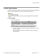
MPC cards
Two MPC-8 cards are preinstalled at the factory. This section describes how to install additional
cards, if required.
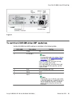
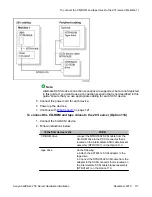
CD-ROM and tape drives
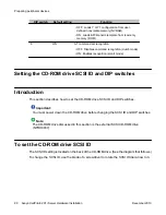
Before you connect CD-ROM and tape drives, ensure that you have set the SCSI ID,
termination, and DIP switches as described in
on page 95.
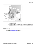
Monitor, keyboard, and mouse
Connect the monitor, keyboard, and mouse to the 201i server faceplate so that you can:
• observe the 201i server startup process.
• run the Configuration Wizard.
• perform initial administration after installation.
The 201i server is not intended to operate with permanent monitor, keyboard, and mouse
connections. Once you have successfully started and configured the 201i server, remove the
monitor, keyboard, and mouse. For day-to-day administration, use a web browser on a PC that
is connected to the ELAN subnet or Avaya server subnet.
Connecting peripheral devices to the 201i server
108 Avaya CallPilot
®
201i Server Hardware Installation
December 2010