


Connecting peripherals to the server
Rear panel connectors
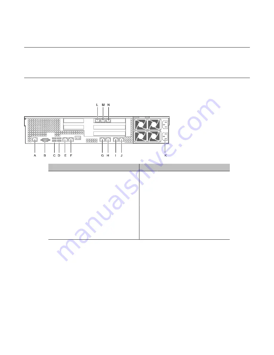
The following diagram shows the connectors on the rear panel.
Label
Control or feature
Label
Control or feature
A
RJ-45 Serial A Connector
I
Not connected
B
Rear Video
J
HB2
C
Dual USB port
K
Power Receptacles
D
Dual USB port
L
MPB96-1 DS30-3
E
ELAN
M
MPB96-1 DS30-2
F
CLAN
N
MPB96-1 DS30-1
G
HB1
H
Mirror
To connect the mouse, keyboard, and monitor to the server
1. Place the monitor, keyboard, and mouse in the same location as the server.
2. Plug the keyboard cable into the lower USB port labeled C and the mouse cable
into the upper USB port labeled C on the rear panel (see Rear panel connectors).
3. Plug the monitor into the video connector on the rear panel. Tighten the screws on
the connector.
4. Ensure that a single-point ground reference is available for all the power outlets
serving the CallPilot server and its peripherals. Before the CallPilot server
installation, a qualified electrician must implement the single-point ground reference
Installing the server and peripheral devices
32 Avaya CallPilot® 1006r Server Hardware Installation
December 2010