


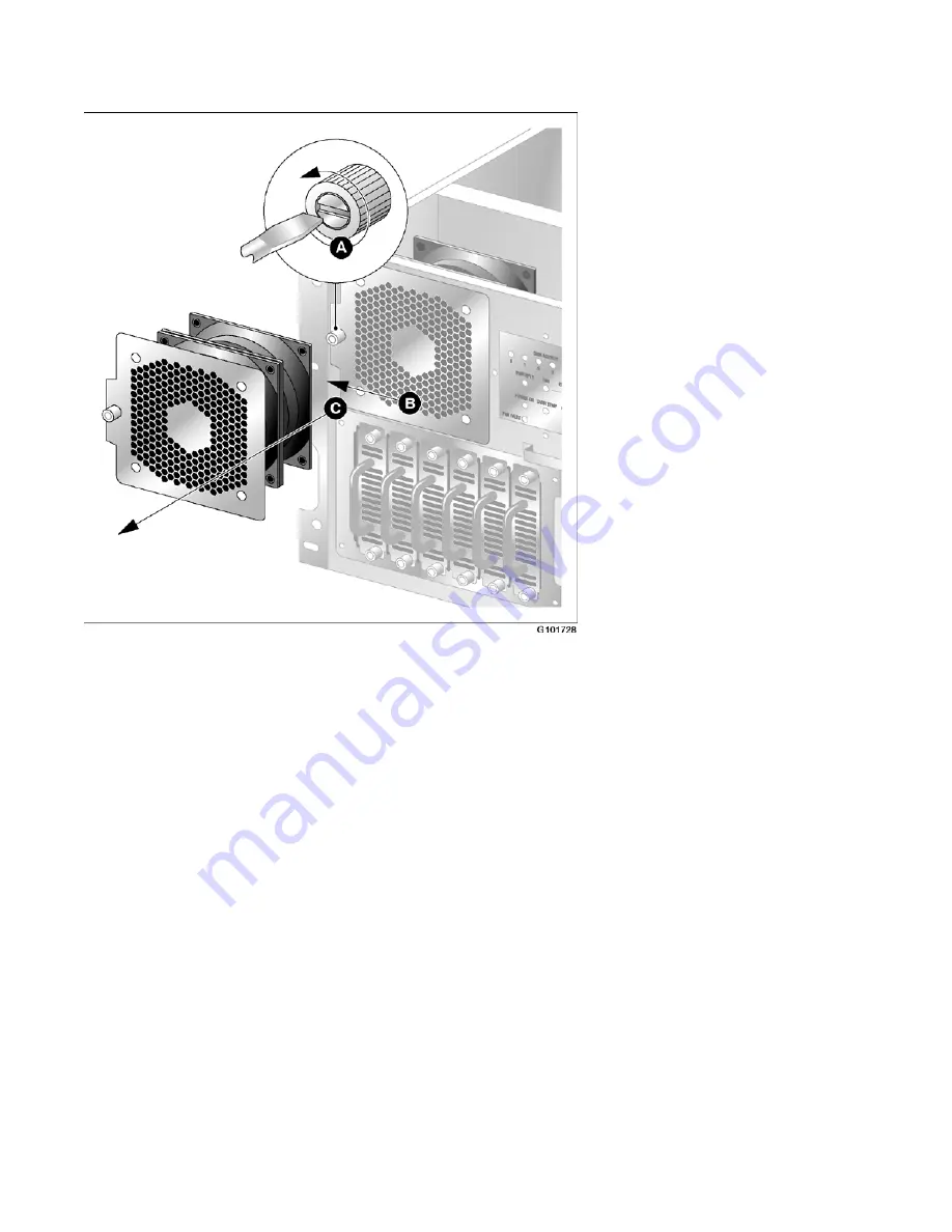
Figure 17: Cooling fan thumbscrew
4. Unseat the cooling fan module by sliding the module horizontally away from the
display and toward the rack rail (see B in the diagram).
Result: The module power connector unseats from the power connector located
behind the display and LEDs.
5. Slide the failed cooling fan module out of the chassis (see C in the diagram).
6. Align the replacement cooling fan module tabs with the four support slots on the
chassis.
Ensure that the module is oriented with the thumbscrew, and insert the tabs into the
supporting slots of the chassis.
7. Slide the cooling fan module toward the front panel display and into position.
Result: The fan module connects with slight resistance. The fans rotate and pull air
into the chassis. The cooling fan LED goes out.
8. Tighten the module thumbscrew and replace the front bezel.
Replacing basic chassis components
88 Avaya CallPilot® 1002rp Server Maintenance and Diagnostics
December 2010
Summary of Contents for callpilot 1002rp
Page 1: ...Avaya CallPilot 1002rp Server Maintenance and Diagnostics 5 0 NN44200 701 01 05 December 2010 ...
Page 4: ...4 Avaya CallPilot 1002rp Server Maintenance and Diagnostics December 2010 ...
Page 10: ...10 Avaya CallPilot 1002rp Server Maintenance and Diagnostics December 2010 ...
Page 18: ...About this guide 18 Avaya CallPilot 1002rp Server Maintenance and Diagnostics December 2010 ...
Page 118: ...RAID operations 118 Avaya CallPilot 1002rp Server Maintenance and Diagnostics December 2010 ...


