


INSTALLATION
Avaya 9130 EBM Site Preparation, Installation and Operator’s Manual
S
164201770 Rev 1
21
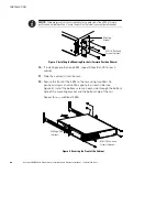
13.
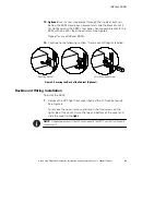
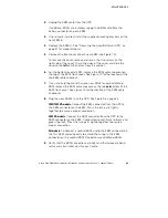
Optional.
Insert a rear stop bracket through the inside of each rail
behind the EBM. Rotate each bracket and slide the bracket until it
fits tightly against the EBM’s rear panel. Secure each bracket to the
EBM with one M3
×
8 pan-head screw. See Figure 5.
Repeat for any additional EBMs.
14.
Continue to the following section, “Rackmount Wiring Installation.”
Rear Stop Bracket
M3
×
8 Pan-Head Screw
Figure 5. Securing the Back of the Cabinet (Optional)
Rackmount Wiring Installation
To install the EBM:
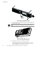
1.
Remove the UPS right front cover (behind the LCD control panel).
See Figure 6.
To remove the cover, remove and retain the two screws on the
right side of the cover. Grasp the top and bottom of the cover and
slide the cover to the
right
.
NOTE
A ribbon cable connects the LCD control panel to the UPS. Do not pull on the cable
or disconnect it.
Summary of Contents for 9130 EBM
Page 47: ......
Page 48: ...1642017701 164201770 1...