


INSTALLATION
Avaya 9130 EBM Site Preparation, Installation and Operator’s Manual
S
164201770 Rev 1
19
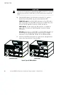
2.
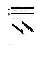
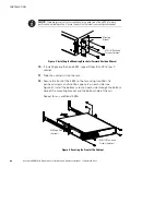
Select the proper holes in the rack for positioning the EBM in the
rack (see Figure 2). The rails occupy four positions on the front and
rear of the rack.
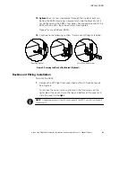
3.
Secure one rail assembly to the front of the rack with one
M6
×
16 pan-head screw and one M6 cage nut.
4.
Using two M6 cage nuts and two M6
×
16 pan-head screws, attach
the rail assembly to the rear of the rack.
M6
×
16 Pan-Head
Screws (6 places)
Front of Rack
M6 Cage Nuts
(6 places)
Tighten
adjustment
screws after rail attachment
(3 places each rail).
Position 4
Position 1
Figure 2. Securing the Rails
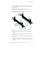
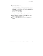
5.
Repeat Steps 3 and 4 for the other rail assembly.
6.
Tighten the three adjustment screws in the middle of each rail
assembly.
7.
If installing more than one EBM, repeat Step 1 through Step 6 for
each rail kit.
8.
Place the EBM on a flat, stable surface with the front of the cabinet
facing you.
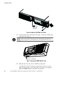
9.
Align the mounting brackets with the screw holes on each side of
the EBM and secure with the supplied M4
×
8 flat-head screws (see
Figure 3).
Summary of Contents for 9130 EBM
Page 47: ......
Page 48: ...1642017701 164201770 1...