• two or four wire tie trunks
• 4-wire E and M Trunks:
- Type I or Type II signaling
- duplex (DX) signaling
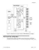
• paging (PAG) trunks
Type I signaling uses two signaling wires plus ground. Type II and DX signaling uses two pairs
of signaling wires. Most electronic switching systems use Type II signaling.
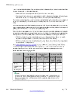
The following table lists the signaling and trunk types supported by the NT8D15 E and M Trunk
card.
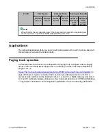
Table 181: Trunk and signaling matrix
Signaling
Trunk types
RLM/RLR
TIE
PAG
CSA/CAA/CAM
2-wire E and M
Yes
Yes
Yes
Yes
4-wire E and M
Yes
Yes
No
Yes
Legend:
RLM Release Link Main
RLR Release Link Remote
CSA Common Control Switching Arrangement
CAA Common Control Switching Arrangement with Automatic Number Identification (ANI)
CAM Centralized Automatic Message Accounting (CAMA) trunk
Physical description
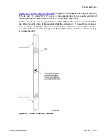
The line interface and common multiplexing circuitry is mounted on a 31.75 cm by 25.40 cm
(12.5 in. by 10 in.) printed circuit board.
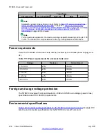
The E and M Trunk card connects to the backplane through a 160-pin connector shroud.
External equipment connects to the card at the back of the Media Gateway using a 25-pin
connector. Telephone lines from station equipment cross connect to the OPS analog line card
at the MDF using a wiring plan similar to that used for line cards. See
Communication Server
1000M and Meridian 1 Large System Installation and Configuration
(NN43021-310) for
termination and cross connect information.
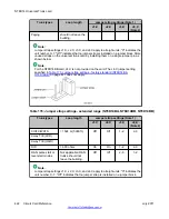
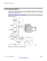
Each card provides four circuits. Each circuit connects with the switching system and with the
external apparatus by an 80-pin connector at the rear of the pack. Each trunk circuit on the
card connects to trunk facilities by tip and ring leads which carry voice, ringing, tone signaling
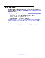
and battery. Trunk option selection is determined by software control in LD 14.
NT8D15 E and M Trunk card
432 Circuit Card Reference
July 2011
Summary of Contents for 1000 Series
Page 1: ...Circuit Card Reference Nortel Communication Server 1000 7 0 NN43001 311 04 04 July 2011 ...
Page 20: ...20 Circuit Card Reference July 2011 ...
Page 30: ...Introduction 30 Circuit Card Reference July 2011 Comments infodev avaya com ...
Page 116: ...Option settings 116 Circuit Card Reference July 2011 Comments infodev avaya com ...
Page 143: ...Figure 25 CP PIV card front Physical description Circuit Card Reference July 2011 143 ...
Page 148: ...NT4N39AA CP Pentium IV Card 148 Circuit Card Reference July 2011 Comments infodev avaya com ...
Page 287: ...Figure 86 Clock Controller Option 3 Operation Circuit Card Reference July 2011 287 ...
Page 302: ...NT5K21 XMFC MFE card 302 Circuit Card Reference July 2011 Comments infodev avaya com ...
Page 346: ...NT6D80 MSDL card 346 Circuit Card Reference July 2011 Comments infodev avaya com ...
Page 353: ...Figure 96 NTDK16 DLC Functional description Circuit Card Reference July 2011 353 ...
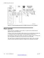
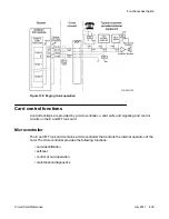
Page 461: ...Figure 147 Paging trunk operation Applications Circuit Card Reference July 2011 461 ...
Page 462: ...NT8D15 E and M Trunk card 462 Circuit Card Reference July 2011 Comments infodev avaya com ...
Page 500: ...NTAK09 1 5 Mb DTI PRI card 500 Circuit Card Reference July 2011 Comments infodev avaya com ...
Page 512: ...NTAK10 2 0 Mb DTI card 512 Circuit Card Reference July 2011 Comments infodev avaya com ...
Page 534: ...NTAK79 2 0 Mb PRI card 534 Circuit Card Reference July 2011 Comments infodev avaya com ...
Page 550: ...NTBK22 MISP card 550 Circuit Card Reference July 2011 Comments infodev avaya com ...
Page 560: ...NTBK50 2 0 Mb PRI card 560 Circuit Card Reference July 2011 Comments infodev avaya com ...
Page 595: ...Figure 165 MGC block diagram Introduction Circuit Card Reference July 2011 595 ...
Page 662: ...NTRB21 DTI PRI DCH TMDI card 662 Circuit Card Reference July 2011 Comments infodev avaya com ...
Page 668: ...NTVQ01xx Media Card 668 Circuit Card Reference July 2011 Comments infodev avaya com ...
Page 700: ......

