background image

Distribution Amplifier (DA)

User Manual 


User Manual


Distribution Amplifier 

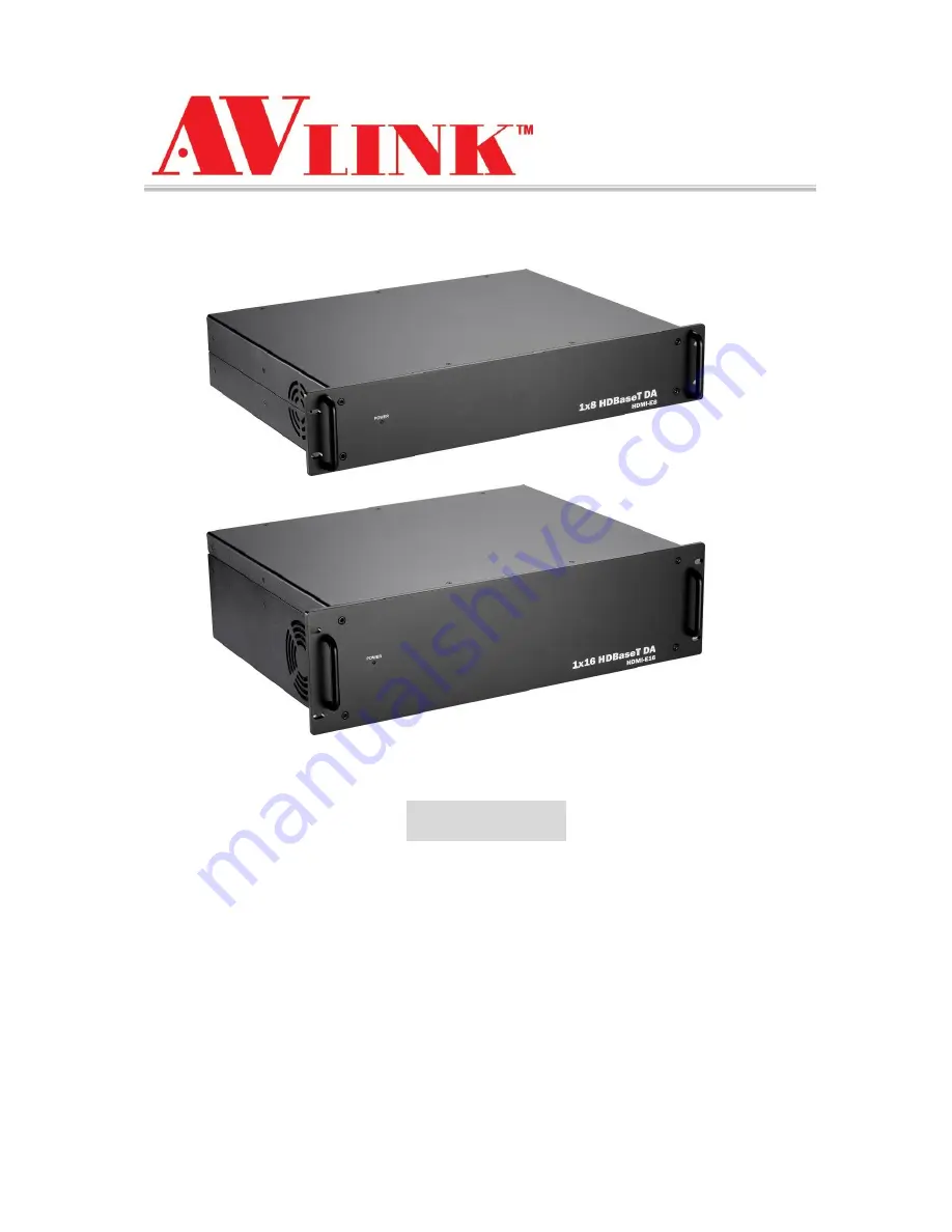
1x8


/


1x16


HDMI-E8 / HDMI-E16 

V.2012HDMI-E8E16.00 

Copyright and Trademarks: 

All rights reserved by C&C TECHNIC TAIWAN CO., LTD. No part of this document may 
be reproduced in any form or by any means without written permission from the product 
manufacturer. Changes are periodically made to the information in this document.  
They will be incorporated in subsequent editions. The product manufacturer may make 
improvements and /or changes in the product described in this document at any time. 

All the registered trademarks referred to this manual are belonging to their respective 
companies. 

Summary of Contents for HDMI-E16

Page 1: ...reproduced in any form or by any means without written permission from the product manufacturer Changes are periodically made to the information in this document They will be incorporated in subsequen...

Page 2: ...d do not use near water It is better to keep it in a dry environment The system should be installed indoor only Install either on a sturdy rack or desk in a well ventilated place Only use the power co...

Page 3: ...te Control 17 6 6 Ports and Switchers 18 6 6 1 RS 232 18 6 6 2 RS 485 20 6 6 3 LAN Port 22 6 6 4 DIP Switcher 8 Pins 23 6 6 5 DIP Switcher 2 Pins 23 6 6 6 Device ID Settings 24 7 Application Software...

Page 4: ...Optional 48 Appendix B IR Mini Controller Optional 49 Appendix C Firmware Upgrade 50 Appendix D RS 232 Communication Protocol 53 D 1 Host Request 53 D 1 1 Device Byte 53 D 1 2 Request Byte 54 D 1 3 I...

Page 5: ...ry devices HDMI E8 HDMI E16 can transmit data or detect signal to over long distances about 100 meters with HDMI extender HX RW HDMI E8 HDMI E16 is used mainly in TV broadcasting projects multimedia c...

Page 6: ...Distribution Amplifier DA 1 HDMI E8 or HDMI E16 Power Cord 1 IR Receiver Cable 1 IR Blaster Cable 1 User Manual 1 1 3 Accessories Optional HDMI Extender HX RW IR Receiver Cable IR Blaster Cable Remot...

Page 7: ...to 4K x 2K 30Hz 8 bit or 1080P 60Hz 12 bit Support original 3D pass through Support High Definition Audio Dolby TrueHD Dolby Digital Plus and DTS HD MA IR pass through supports all IN and OUT ports I...

Page 8: ...6 Weight HDMI E8 4250g HDMI E16 7500g Dimensions LxWxH HDMI E8 332x482x87mm HDMI E16 336x482x130mm Full rack wide without grips Multimedia Max Resolution 4K x 2K 30Hz 8 bit Highest TMDS Frequency 300M...

Page 9: ...as a black metallic housing It can be placed on a sturdy desk directly or installed on a 2U HDMI E8 or 3U HDMI E16 19in bracket See below Figure 4 1 Mount the Device on a Standard Bracket with 2U Rack...

Page 10: ...r DA User Manual 9 5 Front Rear Panels 5 1 Front Panel Figure 5 1 HDMI E8 Front Panel Figure 5 2 HDMI E16 Front Panel HDMI E8 HDMI E16 supports a power LED indicator on the Front Panel allowing you to...

Page 11: ...phics workstation and number display The output jacks allow you to connect to extensible accessory devices for over long connections with terminals just like projectors video recorders displays multip...

Page 12: ...ut jack is connected to the Blu ray player DVD player STB or other source device HDMI Type A Pin Definitions Pin Signal Pin Signal 1 TMDS Data2 11 TMDS Clock Shield 2 TMDS Data2 Shield 12 TMDS Clock 3...

Page 13: ...s Connections Figure 6 1 HDMI E8 Connections Figure 6 2 HDMI E16 Connections The HDMI E8 HDMI E16 supports up to 4 8 Output modules for reparation or upgrade Each module can be configured individually...

Page 14: ...player graphics workstation or number display Use the Cat 5e cable to connect the output RJ45 jack No 1 No 8 or 16 to the RJ45 jack of HDMI Extenders HX RW Through the HDMI extender HX RW you can exte...

Page 15: ...2 Output Cable HDBaseT was designed to provide Full HD performance up to 100 meters of Cat 5e or superior cables In a typical installation the cable is stretched to its full length between the HDBase...

Page 16: ...r hand IR Blaster cable can be connected to IR Tx port on the rear panel Support you an IR channel to control the player from TV or control the TV from player Support all kinds of IR frequency band IR...

Page 17: ...r You can connect IR Receiver cable to the IR EXT port located on the rear panel for optional IR aiming position Figure 6 7 IR EXT Connection The IR EXT Connection is applied to Remote Controller 6 4...

Page 18: ...f the Distribution Amplifier DA The computer can then be used to control the Distribution Amplifier DA Figure 6 9 RS 232 and Control PC connection Distribution Amplifier DA also supports a LAN port al...

Page 19: ...cation ports Use the RS 232 or RS 485 serial communication port to carry out remote operation 6 6 1 RS 232 The RS 232 Pin functions are described as below Pin No Abbreviation Description 1 N u Null 2...

Page 20: ...Distribution Amplifier DA User Manual 19 Figure 6 11 b RS 232 From Female DB9 PC to Male DB9 DA Figure 6 12 RS 232 From Female DB25 PC to Male DB9 DA The DA RS 232 port is defined by DCE...

Page 21: ...d can be used effectively over long distances and in electrically noisy environments This Distribution Amplifier DA supports up to two RS 485 ports allows you to control more than one relative product...

Page 22: ...Distribution Amplifier DA User Manual 21 Figure 6 14 RS 485 Connection for HDMI E16 Figure 6 15 RS 485 Connection for HDMI E8 and HDMI E16...

Page 23: ...X Received Data RS 232 and RS 485 baud rates 9600bps no odd or even calibration address 8bit data transmission address 1bit stop address 96 N 8 1 6 6 3 LAN Port This Distribution Amplifier DA supports...

Page 24: ...232 port and LAN port connection ON RS 232 OFF LAN D DIP Switcher Pin 8 Reset the web server IP address to 192 168 0 3 The steps are as below 1 Please adjust the pin8 to ON and re start the Distributi...

Page 25: ...01 ON ON ON ON OFF 2 02 00010 ON ON ON OFF ON 3 03 00011 ON ON ON OFF OFF 4 04 00100 ON ON OFF ON ON 5 05 00101 ON ON OFF ON OFF 6 06 00110 ON ON OFF OFF ON 7 07 00111 ON ON OFF OFF OFF 8 08 01000 ON...

Page 26: ...Distribution Amplifier DA User Manual 25 27 1B 11011 OFF OFF ON OFF OFF 28 1C 11100 OFF OFF OFF ON ON 29 1D 11101 OFF OFF OFF ON OFF 30 1E 11110 OFF OFF OFF OFF ON 31 1F 11111 OFF OFF OFF OFF OFF...

Page 27: ...perating environment is as below Window 98 2000 NT XP 7 8 operating systems For Windows 7 8 please use AV Matrix 3 0 00 version at least 32M internal memory or above 10M hard disk space or above CD RO...

Page 28: ...RS 232 Refer to the previous section 6 6 1 RS 232 7 2 Configuration After finishing installation click to active AV Matrix Application In the Options window select the connected PC Port number and Bau...

Page 29: ...O Plug Enable to detect the status of all output ports for audio video Version Show the version information of Distribution Amplifier DA The functions as below are not supported for Distribution Ampli...

Page 30: ...nput number key 001 to the bottom Then press consecutively the previously selected Output number keys 002 003 and 004 This way you have selected IN1 to OUT2 3 and 4 configurations Upon completion of t...

Page 31: ...of main configuration window will show you the detected information presently Options Allows you to configure the Port number and Baud rate Exit Click this button to exit the configuration window Sav...

Page 32: ...re 7 4 a below Figure 7 4 a Disconnect Function Key for HDMI E8 Reference Follow the steps as below to disable the output ports including port 003 002 and 001 Step 1 First press down the output number...

Page 33: ...Distribution Amplifier DA User Manual 32 The final results will be as shown in Figure 7 4 b below Figure 7 4 b Disconnect Function Key for HDMI E8 Reference...

Page 34: ...adjust Volume Bass Treble Subwoofer and Delay by sliding the scrollbar You can also enable disable the Mute function here Figure 7 5 Audio Configuration Window Mute Function Description To mute the v...

Page 35: ...e One Port Configuration A specific example of Mute all function is described below Click Select all check box all of configuration sections will become as light blue block then click Mute check box t...

Page 36: ...Distribution Amplifier DA User Manual 35 Figure 7 7 Mute All Ports Configuration...

Page 37: ...ed synchronously Beside all ports for EDID functions are also processed entirely You cannot configure the port separately FIX mode The Matrix Switcher will supply a set of fixed EDID values to support...

Page 38: ...ion 1 First select Location 1 as shown below Then click the Save key to save all the present input output switching relations to Location 1 Figure 7 9 Retrieve Function Description To retrieve the sav...

Page 39: ...n in Figure 7 12 a Figure 7 12 Options a Figure 7 12 Options b Function Description Linking Methods In Port number select one of the COM ports as shown in Figure 7 12 b for an example in Baud rate sel...

Page 40: ...er located on the rear panel Beside please adjust the DIPs to LAN and Master for the web control device Set Click this button to set the connected combinations both output and input ports OFF Disable...

Page 41: ...ue click Enable to take effect For HDMI E8 is useful from 1 to 8 values upon 8 output ports and HDMI E16 is useful from 1 to 8 values upon 8 output ports Previous and Next If the connections of your M...

Page 42: ...Used If the Matrix Switcher does not support video function it will appear Not Support The Change button will useless Figure 7 18 Video Configuration Not Support 7 3 3 Device Status Information Click...

Page 43: ...N Main Operation Refer to the main configuration window for the basic operation is described as below Example Now there is a Distribution Amplifier DA having all the input output ports properly connec...

Page 44: ...ut switching relations to Location 2 First select Location 2 as shown in the figure below Then click the Save button to save the present input output switching relations to Location 2 Retrieve Functio...

Page 45: ...twork Settings In the Network Settings window you can set the IP information by yourself Fix IP or click the Enable DHCP check box to get the IP from the DHCP Float IP Click the Default button to rest...

Page 46: ...entire connected Device name will be showed on the Console List as Figure 7 25 For this model the software utility will show at least 1 up to 32 devices The example as below shows you an ID 0 for the...

Page 47: ...n or the connector gets loosen You are advised to replace the connection cable 3 Check if the output port number is the same as the controlled port number 4 Check the connections of input and output p...

Page 48: ...ocation If it is still not to be improved please check with the build in fan whether is damaged Or contact your agency for helping 7 What to do if IR function failure occurred Answer Check the remote...

Page 49: ...ntrol interface allows you to control the channels and video features switch of device through remote controller For the switching you can press OUT key then press IN key OUT 0 OUT 9 and ALL keys are...

Page 50: ...ni Controller is only available to the IR Receiver connected to the IR1 IN or IR2 IN port of HDMI Extender HX RW If there are over 2 IR Receivers receive the signal all of them will be switched to the...

Page 51: ...your device from web server Follow the steps as below to upgrade the firmware 1 Open the Browser on your PC key in the default IP address http 192 168 0 3 to login the AV MA TRIX Control configuratio...

Page 52: ...31 for upgrading firmware 5 Select 2 Matrix I O Module will allow you to upgrade I O modules You have to decide which device you want to configure and then select the suitable Device ID and I O Modul...

Page 53: ...nformation will appear as below Besides the firmware upgrade will not stop even though the web connection is fail suddenly 7 If there is a firmware already exists on the web server during firmware upg...

Page 54: ...keys for operation you are also permitted to use the RS 232 connection port for remote operation D 1 Host Request A standard command is 5 bytes Device Request Index Value CRC Byte 1 Device Byte DB By...

Page 55: ...o Status Setting Memory A 2 3 0x05 Recall Video Status Setting Memory A 2 0x06 Recall Audio Status Setting Memory A 2 0x07 Request Video Output Channel Output Memory B 0x08 Request Audio Output Channe...

Page 56: ...2 A 2 0X1F Request Audio Output Delay High Output Memory B Video Control 0x20 Select Input EDID Type 0 EDID A 2 0x21 Request Input EDID Type 1 0 B Device Information 0x30 Request Protocol Version 0 0...

Page 57: ...quest List and Table Command Index List Table Command Index List Index Description Output The output that will be selected Port 1 1 Port 2 2 Port n n 0 All outputs Input The input that will be selecte...

Page 58: ...Current Status Can t be stored Enable 1 Enable Status example Mute Plug 0 Disable Status example Unmute Unplug Level Level Range 0 100 0x81 Increase a step 0x82 Decrease a step Delay Audio delay time...

Page 59: ...AC 2F 71 93 CD 90 11 4F AD F3 70 2E CC 92 D3 8D 6F 31 B2 EC 0E 50 A0 AF F1 13 4D CE 90 72 2C 6D 33 D1 8F 0C 52 B0 EE B0 32 6C 8E D0 53 0D EF B1 F0 AE 4C 12 91 CF 2D 73 C0 CA 94 76 28 AB F5 17 49 08 56...

Page 60: ...1 CB Type E AB LB EXINF VEINF AEINF PLUG CB D 2 1 ACK Type A ACK Byte CRC Byte Total 2 Bytes Name Bit 7 Bit 6 Bit 5 Bit 4 Bit 3 Bit 2 Bit 1 Bit 0 AB ACC 0 0 Device ID 0 31 CB CRC ACC The devices ackno...

Page 61: ...Response the status refers to the table Request Description Index Value 0x07 Request Video Output Channel 0x08 Request Audio Output Channel Output Input 0x09 Request Video Input Plug Status 0x0A Reque...

Page 62: ...VERB VERC Version Type A RS 232 Protocol Version contains the VER1 and VER2 ex VER1 VER2 VER1 Data 1 Bit 7 Bit 0 Range 0 99 VER2 Data 2 Bit 7 Bit 0 Range 0 99 If the Data 1 is 0x01 and Data 2 is 0x07...

Page 63: ...e data bytes not include the AB LB and CB The maximum LB value of the ACK Type D is 19 INFO Device information Bit 7 1 Support Audio switch tools request Request 0x02 0x04 0x06 and 0x08 0 Not support...

Page 64: ...and 0 The maximum LB is 64 Bytes default 1 The maximum LB is 128 Bytes 2 The maximum LB is 254 Bytes 255 is reserved 3 Reserved The LB value of the Ack packet is not limited by LBMAX If the extended i...

Page 65: ...0 the device support Request 0x04 0x02 and 0x06 0x02 PLUG Plug Detect Support Information VIPD Video input plug detection command flag Request 0x09 1 Support Video input plug detection 0 Not support...

Page 66: ...100 meter away by using an HDMI Extender and Cat 5e cable HDMI Extender is ideal for Test bench facilities Data Center Help desks Front View Rear View LED Indicators Green LED Off Blink On POWER Powe...

Page 67: ...to install easily Specifications Function HX RW HDMI OUT HDMI A Type Female LINK RJ45 Connector IR OUT 3 5 Stereo Jack IR2 IN 3 5 Stereo Jack F W UPGRADE DB9 Female Max Resolution 4K x 2K Cable Dista...

Page 68: ...Cable Directions Plug IR Blaster Cable into HDMI Extender HX RW IR OUT port located on the front panel IR Blaster Cable NC P N HDMI Output Connector Pin Signal Pin Signal 1 TMDS Data 2 11 TMDS Clock...

Page 69: ...8 Brown However sometimes especially in demonstrations or in a lab environment the cable is rolled randomly in small turns for convenience The randomly rolled UTP cable suffers additional signal impai...

Page 70: ...xtender HX RW firmware 1 Connect the power cord to the power port on the panel of HDMI Extender HX RW The other end of the power cord connected to a suitable power source 2 Connect the control PC and...

Page 71: ...Distribution Amplifier DA User Manual 70 5 The burning windows will pop up and begin to upgrade 6 Final the burning is finish as below...

Reviews: