


Applying Ladder Logic
31
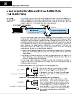
Using the OP-1212 with an Allen-Bradley PLC
Integer type of files can be mapped for the Allen-Bradley PLC when being used with
the OP-1212. In the examples below, integer file registers starting at base address
N7:0
have been mapped. If you need more information on any of the features of the
panel, refer to
Understanding the OP-1212 Panel
in this manual.
bit
1
2
3
4
5
6
7
8
9
10
11
12
device number
0
1
2
3
4
5
6
7
8
9
10
11
12
13
14
15
N7:0
N7:4
Pushbutton 7
6
2
Light Lamp 4
N7:0
3
I:0
Light LED 9
N7:2
8
3
I:0
Light Lamp 5
Add flashing
N7:0
N7:1
I:0
4
4
1
2
N7:4
O:3
N7:5
I:0
Pushbutton 12 ON
Start Process
Process Finished
Pushbutton 7 OFF
N7:5
11
2
5
11
15
1
2
3
4
6
7
8
9
10 11 12
1
2
3
4
5
6
7 8
9 10 11
5
12
N7:0
Indicator Lamp ON/OFF
N7:1
Indicator Lamp Flash
N7:2
N7:3
N7:4
N7:5
Button LEDs ON/OFF
Button LEDs Flash
Button ON/OFF
Force Data & Comm
1
2
3
4
5
6
7
8
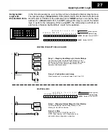
Rung 1 -- Pushbuttons and Lamps
When pushbutton 7 is activated Lamps 3 and 4 turn ON.
Also, the LED in pushbutton 7 will turn ON if LED Separation
is disabled and the pushbutton is configured as maintained.
Rung 2 -- LEDs
When contact I:0/3 is ON, LED 9 turns ON
NOTE: Panel must be in LED Separation mode and pushbutton
configured as momentary.
Rungs 3 and 4 --Flashing Lamps
To flash a Lamp, it must be first turned ON When contact I:0/1 is
activated Lamp 5 will turn ON and when contact I:0/2 is
activated the Lamp will flash.
Rungs 5 and 6 -- Flashing LEDs
To flash a LED, it must be first turned ON When contact I:0/1 is
activated LED 1 will turn ON and when contact I:0/2 is activated the
LED will flash.
NOTE: Panel must be in LED Separation mode and pushbutton
configured as momentary.
Rungs 7 and 8 -- Force Function
When pushbutton 12 is pressed, process O:3/2 is started.When the
process is completed it activates contact I:0/5 which forces
pushbutton 12 OFF.
NOTE: The pushbuttons must be configured as maintained (alternate)
and the panels ”Force Function” feature must be enabled.
I:0
Light LED 1
Add flashing
N7:2
N7:3
I:0
0
0
1
2
Light Lamp 3
0 0 0 0 0 0 0 0 0 0 0 1 1 1 0 0
0 0 0 0 0 0 0 0 0 0 0 1 0 0 0 0
0 0 0 0 0 0 0 1 0 0 0 0 0 0 0 1
0 0 0 0 0 0 0 0 0 0 0 0 0 0 0 1
0 0 0 0 1 0 0 0 0 1 0 0 0 0 0 0
1 0 0 0 1 0 0 0 0 0 0 0 0 0 0 0
Using Ladder
Logic with
Allen--Bradley PLC