


Applying Ladder Logic
27
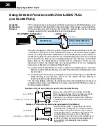
In the following examples, user memory will be remapped to internal relay memory.
The internal relays of
Direct
LOGIC PLCs (DL05, DL06, DL105, DL205, DL350 and
DL405) start at V40600. In the examples below,
V2000
has been used as the base
address for a
Direct
LOGIC PLC, then
SP1
(always ON relay) is used in the ladder
logic to perform the remapping. When using
SP1
, the remapping is performed on
each scan, otherwise
m+0
and
m+1
would not be updated.
1
2
3
4
6
7
8
9
10 11 12
1
2
3
4
5
6
7 8
9 10 11 12
5
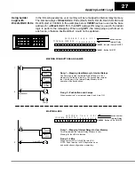
Rung 2 -- Pushbuttons and Lamps
When pushbutton 7 is activated Lamps 3 and 4 turn ON.
Rung 2 -- LEDs
When contact X12 is ON, LED 9 turns ON
NOTE: Panel must be in LED Separation mode
and pushbutton configured as momentary.
C2
C26
C3
Pushbutton 7
OUT
OUT
Lamp 4
Lamp 3
X12
Light LED 9
OUT
C50
1
2
1
2
SP1
V2004
V40601
LD
OUT
V2000
V40600
LD
OUT
Rung 1 -- Mapping User Memory to Internal Relays
The first steps remap the Internal Relay Memory to User
Memory for the lamps to function. The second step remaps
the User Memory to the Internal Relay Memory for the
operation of the pushbuttons.
SP1
V2002
V40602
LD
OUT
Rung 1 -- Mapping Internal Relays to User Memory
This step remaps the Internal Relay Memory to User
Memory for the LEDs to function.
V40600
0
1
2
3
4
5
6
7
Internal Relay
Indicator Lamp ON/OFF
V40601
Button ON/OFF
1
2
3
4
5
6
7
8
9
10
11
12
device number
1
0
0 0 0 0
0 0
0
0
0 0
0
0
0
1
10
11
12
13
14
15
16
17
MAPPING PUSHBUTTONS AND LAMPS
MAPPING LEDS
V40602
Button LEDs ON/OFF
0
1
2
3
4
5
6
7
Internal Relay
1
2
3
4
5
6
7
8
9
10
11
12
device number
10
11
12
13
14
15
16
17
0
0
0 0 0 0
0 0
0
0
0 0
1
0
0
0
0
0
0 0 0 0
0 0
0
0
0 0
1
0
0
0
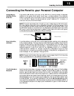
Using Ladder
Logic with
Direct
LOGIC PLCs