


Applying Ladder Logic
26
Using Selected Functions with
Direct
LOGIC PLCs
(not DL305 PLCs)
The “remapping” process has been briefly discussed as a method that allows you to
easily manipulate individual bits to take advantage of the panels several functions.
All the functions are bit-controlled. By using this method, the number of relays
actually needed for the selected functions are consumed.
User Memory
Internal Relay Memory
mapping
mapping
A.
B.
C.
OP--WINEDIT Configuration
Ladder Logic
96 Consecutive Bits
Consumed
Use Only the Words Needed
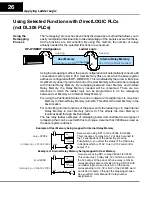
Using the remapping method, the panel configuration will automatically consume 96
consecutive memory bits in PLC User Memory (this occurs when the base register
address is configured with OP--WINEDIT). This is indicated by the arrow A. But since
User Memory doesn’t provide bit control, the User Memory will need to be remapped
with Internal Relay Memory. By remapping between User Memory and Internal
Relay Memory, the Relay Memory needed will be consumed. There are two
directions in which the ladder logic can be programmed to do the remapping
between User Memory and Internal Relay Memory:
For using the Pushbutton Status to control outputs, write ladder logic to map User
Memory to Internal Relay Memory (arrow B). This affects the User Memory in the
m+4
location.
For controlling all other functions of the panel, write the ladder logic to map Internal
Relay Memory to User Memory (arrow C). This affects the User Memory in
locations
m+0
through
m+3
and
m+5
.
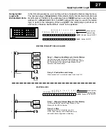
The two relay ladder examples of remapping below demonstrate the two types of
remapping that can be used with this technique. Assume that V2000 was used as
the base register address:
Y12
C102
OUT
SP1
V2004
V40604
LD
OUT
Here we are using SP1 to map V2004 to V40604.
This consumes 16 relay bits, 12 of which are tied to
the 12 pushbuttons of the panel. By pressing
Pushbutton 3, you affect the status of the third relay
in V40604 which is C102. In turn, C102 will control
output Y12.
m+4 =V2004
remapping = V2004:40604
Example of User Memory being mapped to Internal Relay Memory
C2
X12 Light Lamp 3
OUT
SP1
V40600
V2000
LD
OUT
Here we are using SP1 to map V40600 to V2000.
This consumes 16 relay bits, 12 of which are tied to
the 12 Lamps of the panel. When a relay is ON, its
corresponding Lamp is ON. By turning ON X12 with
our ladder logic, we can thus turn on the Lamp
corresponding to C2. C2 is bit 2 of the V40600 word
and is tied to Lamp 3 through the mapping process.
See your PLC User Manual for relay number
assignments
m =V2000
remapping = V40600:V2000
Example of Internal Relay Memory being mapped to User Memory
Using the
Remapping
Process