


Applying Ladder Logic
25
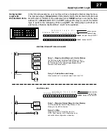
Using All Functions with the DL305 PLCs
When configuring the OP-1212, a base address must be selected in the CPU. This
address can be a
direc
t mapping to the reserved memory locations that are tied to
internal relays. The internal relays of the DL305 family start at
R16
. Using this
method, the total mapping consumes 96 internal relays, of which 75 are assigned to
operator functions. This method should only be used when all of the OP-1212
functions are utilized. In the examples below,
R16
has been chosen as the starting
address for the DL305.
Notice that the internal control relays are numbered in octal
and not decimal.
0 0 0 0 0 0 0 0
0 0 0 1 1 1 0 0
0 0 0 0 0 0 0 0
0 0 0 1 0 0 0 0
0 0 0 0 0 0 0 1
0 0 0 0 0 0 0 1
0 0 0 0 0 0 0 0
0 0 0 0 0 0 0 1
0 0 0 0 1 0 0 0
0 1 0 0 0 0 0 0
1
0
0
0 1 0 0 0
0 0 0 0 0 0 0 0
1
2
3 4
6
7
8
9 10 11 12
1 2 3 4
5 6
7 8
9 10 11 12
5
C162
C266
C163
Pushbutton 7
OUT
OUT
Lamp 4
Lamp 3
IO12 Light LED 9
OUT
C230
IO13 Light Lamp5
Add flashing
OUT
OUT
C164
C204
IO14
IO15 Light LED 1
Add flashing
OUT
OUT
C220
C240
IO14
C273
IO0
C313
IO16
OUT
OUT
Pushbutton 12 ON
Start Process
Process Finished
Pushbutton 12 OFF
C315
OUT
Indicator Lamp ON/OFF
Indicator Lamp Flash
Button LEDs ON/OFF
Button LEDs Flash
Button ON/OFF
Force Data & Comm
1
2
3
4
5
6
7
8
R16
internal relay
1
2
3
4
5
6
7
8
9
10
11
12
device number
0
1
2
3
4
5
6
7
R20
R22
R24
R26
R30
Rung 1 -- Pushbuttons and Lamps
When pushbutton 7 is activated, Lamps 3 and 4 turn ON.
Rung 2 -- LEDs
When contact IO12 is ON, LED 9 turns ON.
NOTE: Panel must be in LED Separation mode and
pushbutton configured as momentary.
Rungs 3 and 4 --Flashing Lamps
To flash a Lamp, it must first be turned ON When contact IO13
is activated Lamp 5 will turn ON and when contact IO14 is
activated the Lamp will flash.
Rungs 5 and 6 -- Flashing LEDs
To flash an LED, it must first be turned ON. When contact
IO15 is activated, LED 1 will turn ON and when contact IO14 is
activated the LED will flash.
NOTE: Panel must be in LED Separation mode and
pushbutton configured as momentary.
Rungs 7 and 8 -- Force Function
When pushbutton 12 is pressed, process IO0 is started.When the
process is completed, it activates contact IO16 which forces
pushbutton 12 OFF.
NOTE: The pushbuttons must be configured as maintained
(alternate) and the panels ”Force Function” feature must be enabled.
0
1
2
3
4
5
6
7
R17
R21
R23
R25
R27
R31
Using Ladder
Logic