


Understanding the OP- 1212
18
Another feature of the Lamps is there ability to flash. This feature is also controlled
via your ladder logic. The flashing feature requires that the lamp is activated first,
then the corresponding bit in memory location
m+1
is activated. Again, this
accomplished by activating a coil.
Each of the 12 pushbuttons on the OP-1212 have corresponding LEDs located on
the upper left hand corner. The LEDs are usually used as an indication of the
pushbutton status however, they can be configured to work independently. When
configuring the OP-1212 panel, you have the option to select
LED separation
mode
. If this option is selected, the LEDs will work in the same manner as the Lamps
using the ladder logic to control the status of the LED. Also, the pushbutton itself
must be configured as a momentary pushbutton
. To activate an LED in this
configuration, the appropriate bit in memory location
m+2
must be energized.
Just like the Lamps, the LEDs have the ability to flash. This feature is also controlled
via your ladder logic. The flashing feature requires that the LED is activated first
(memory location
m+2
), then the corresponding bit in memory location
m+3
is
activated. Again, this is accomplished by activating a coil. As mentioned previously,
the LED is used for the status of its associated pushbutton unless it is configured for
LED separation mode
. This also applies to flashing the LEDs independently of the
pushbuttons.
The OP-1212 has the capability to “force” a pushbutton ON or OFF through your
ladder logic. For example, you might have a pushbutton that starts a process, and
you want to turn it off after the process has completed. Pressing the pushbutton
would start the process (turns the pushbutton ON) and the ladder logic would turn
the pushbutton OFF after the process was complete. Since the pushbuttons
must
be configured as maintained (alternate)
for the force function to work, the process
would be halted until the pushbutton was activated again. The force function feature
and pushbutton option is enabled during the configuration of the panel.
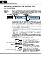
There are three modes of force function available which are located in the three
most significant bits of memory location
m+5
.
Mode 1 (M1)-forces all Pushbuttons to reflect the status
stored in
m+5
. For
example, the data shown below would force Pushbuttons 3, 4 and 12 to ON and all
the others would be forced OFF. Notice that bit M1 of
m+5
is set to 1 for this mode. M2
and M3 are set to 0’s.
Mode 2 (M2)-forces ON only those Pushbuttons matching the bits set
in
register
m+5
. The bits not set do not affect the status of the Pushbuttons. You would
set M2 to 1 while M1 and M3 are set to 0.
Mode 3 (M3)-forces OFF only those Pushbuttons matching the bits set
in
register
m+5
. The bits not set do not affect the status of the Pushbuttons. You would
set M3 to 1 while M1 and M2 are set to 0.
m+5
Force Function
Registers
1
1
0
0
0
0
0
0
0
0
0
1
0
0
0
1
1
2
3
4
5
6
7
8
9
10
11
12
pushbutton number
M2
M1
M3
NOTE:
F
orcing is similar to a one-shot process. That is, once you have set the mode
in m+5, the bit patterns in m+4 are changed (according to the mode selected), and
then, all of the bits in m+5 are set to zero. What this means is that all pushbuttons
return to normal manual operation after the forcing is completed.
Flashing the
Lamps
LEDs and
Separation Mode
Flashing the LEDs
Force Functions