


Installing the Panel
15
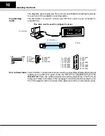
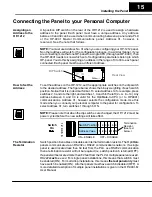
Connecting the Panel to your Personal Computer
A 6-position DIP switch on the rear of the OP-1212 is used to assign a hardware
address to the panel. Each panel must have a unique address. Any address
between 0 and 30 can be used when communicating between a panel and a PLC
or the OP-9001 Master Communications panel. Address 31, however, is
reserved. See the note that follows.
NOTE:
You must use Address No. 31 when you are configuring your OP-1212 panel.
No other address will work for the configuration process. In a similar manner, if you
are connecting more that one OP-panel to a single CPU (through an OP-9001), then
the OP-9001 needs to know which set of configuration parameters belong to which
OP-panel. You do this by assigning an address in the range of 0 to 30 to each panel
connected. Each panel must have a different address.
DIP Switch
Rear View
To set the address on the OP-1212, set the apppropriate switches on the dip switch
to the desired address. The figure below shows the binary weighting of each switch
position. Notice that it is in decimal format. To select address 14 for example, press
switches 2, 3 and 4 to the right, and switches 1, 3 and 5 to the left (2 + 4+ 8 = 14). Any
address between 0 and 30 is valid for the OptiMate-to-CPU (or to OP9001)
communications. Address 31, however selects the configuration mode. Use this
mode when you connect your personal computer to the panel for configuration. To
select address 31, turn switches 1 through 5 ON.
NOTE:
Please note that when the dip switches are changed, the OP-1212 must be
power cycled before the new settings will take effect.
123456
ON = ENABLE
OFF = DISABLE
Switch
On
Switch Position
1 2 3 4 5 6
Address Value
1 2 4 8 16 T
Termination
Resistor.
(See text
below.)
Switch position 6 enables or disables an internal termination resistor. The OptiMate
panels communicate via an RS232 or RS422 communcations network. If a single
panel is used located less than 50 feet from the PLC, use RS232 communication
then a termination resistor will not be required (i.e. switch position 6 is turned OFF).
If a panel will be located more than 50 feet from the PLC or multiple panels are used,
RS422
must
be used.
For single panel installations, this means that switch 6 must
be enabled (ON). For multi-drop installations, this means
the last panel only
must
have switch 6 enabled (ON). All other panels must have switch 6 disabled (OFF). A
more detailed description of multiple panel installations is given in the OP-9001-M
User Manual.
Assigning an
Address to the
OP-1212
How to Set the
Address
The Termination
Resistor