Chapter 3: Component Configuration and Wiring
DURA
pUlse
Drives Dynamic Braking User Manual
3–9
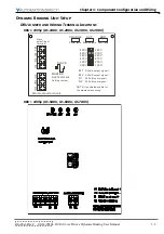
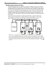
Basic Braking Wiring Diagram
L1
L2
L3
NFB
MC
Thermal
Overload
Relay*
– OR –
Braking Resistor
Thermostat
Surge
Suppressor
DURA
PULSE
AC Drive
DURApulse
Dynamic
Brake Unit
Braking
Resistor
AC MOTOR
L1
L2
L3
T1
T2
T3
IM
Thermal
Overload
Relay*
– OR –
GS-xxxx-BR-ENC
Braking Resistor
Thermostat
N.C. Contact
O.L.*
BR
B1
B2
+(P) / DC+
–(N) / DC–
RA
RB
+(P)
–(N)
DI3
(External
Fault)
DCM
MC
O.L.*
– OR –
Braking Resistor
Thermostat
N.C. Contact
SA
Non Fused Breaker
Control circuit terminal
Main circuit (power) terminals
RC
M1 M2
S1
S2
Grounding
resistance
less than
0.1
Master/Slave Terminals used between
multiple Dynamic Brake Units (if required)
Alarm
Relay
Shielded leads
Motor grounding
terminal
* Although it is recommended, the use of a thermal overload relay in line with the braking resistor is not required.
GS-xxxx-BR-ENC braking resistors include a thermostat for thermal protection of the braking resistor, and are the preferred
method of protection when available. Orient the braking resistors such that the thermostat is above the resistors in the
enclosure, as this will ensure that the thermostat is exposed to the rising air temperature produced by the resistors.
Grounding
terminal on
brake unit
enclosure
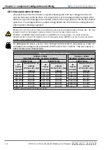
Smaller-capacity DURApulse AC Drives can connect directly to braking resistors, and
do not require Dynamic Braking Units for braking. Refer to the “Dynamic Braking
Component Selection” section of Chapter 1 to determine which braking components are
required for each drive.
Although it is recommended, the use of a thermal overload relay in line with the braking
resistor is not required. GS-xxxx-BR-ENC braking resistors include a thermostat for
thermal protection of the braking resistor, and are the preferred method of protection
when available. Orient the braking resistors such that the thermostat is above the
resistors in the enclosure, as this will ensure that the thermostat is exposed to the rising
air temperature produced by the resistors.
For overload relay information, Refer to the “Overload Relay” section at the beginning
of this chapter.
Summary of Contents for DURA PULSE GS-2DBU
Page 1: ...Dynamic Braking User Manual GS DB_UMW...
Page 2: ...BLANK PAGE...
Page 6: ...W 4 DURApulse Drives Dynamic Braking User Manual 2nd Ed Rev C 06 14 2019 BLANK PAGE...
Page 49: ...2nd Ed Rev C 06 14 2019 DURApulse Drives Dynamic Braking User Manual BLANK PAGE...
Page 50: ...DURApulse Drives Dynamic Braking User Manual 2nd Ed Rev C 06 14 2019...

