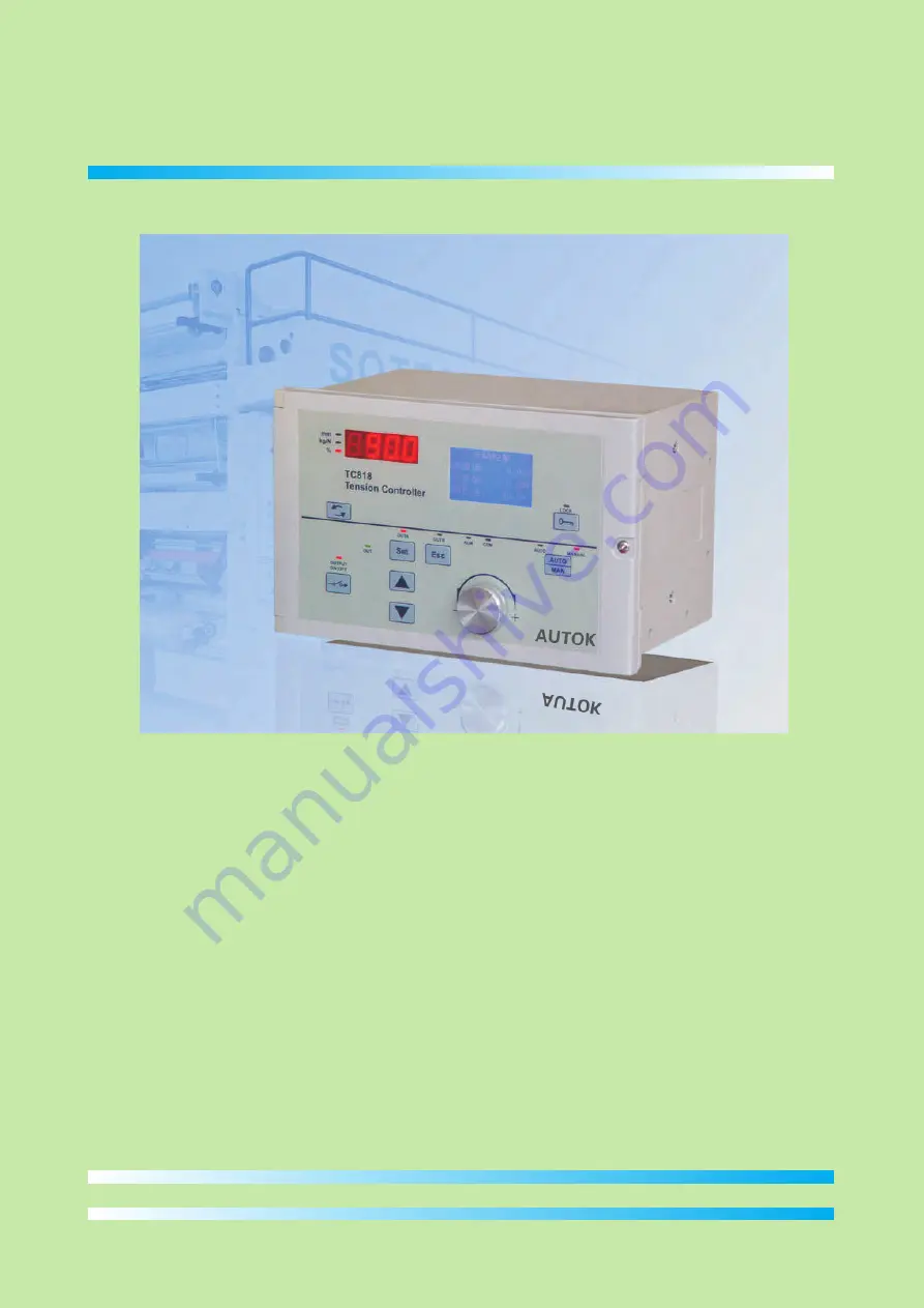
TC818
TENSION CONTROLLER
INSTRUCTION MANUAL(V4.00)
Page 1: ...TC818 TENSION CONTROLLER INSTRUCTION MANUAL V4 00 ...
Page 2: ...creens 8 4 2 Operation 15 4 3 Taper tension control 23 5 Diameter Tension Control 24 5 1 Introduction 24 5 2 Roll radius monitoring 25 5 3 Basic operations 27 5 4 Constant tension control 28 5 5 Taper tension control 29 5 6 Program tension control 30 6 Additional functions 32 7 Serial communications 33 8 Appendices 37 8 1 Parameters screen 37 8 2 Troubleshooting 38 8 3 Technical specifications 39 ...
Page 3: ...utch directly with its built in Powder brake Powder brake Proximity switch Automatic Tension Control Radius Tension Control ad cell Lo 128x96 graphic LCD Chinese and English Diameter tension control menu easy to use RS232 RS485 communication interface the Full digital circuits no potentiometer controller can be used to form Distributed Control System DCS with PLC and PC input can be used Two reel ...
Page 4: ...485 None RS232 interface 3 wires RS485 interface 2 wires Meaning 4 Communication Code V1 00 V2 00 V3 00 Radius tension controller Automatic tension controller Automatic and Radius tension controller Meaning 5 Software Version 24V 36V 0 Code 24V 4A drive magnetic powder brake clutch 36V 3A drive magnetic powder brake clutch None Meaning 1 Main Output 3 Code examples 1 TC818 36V 0 0 0 V3 00 designat...
Page 5: ...lector is pressed The type of contents displayed is indicated by the Content LED provided on the left side of the 7 seg display kg N measured tension in kg or Newton output mm radius in mm 5 LOCK key and Indicator This key is used to lock unlock the keypad except the LED display selector Lock indicator is on keypad locked Lock indicator is off keypad unlocked If set Function 29 to Radius control i...
Page 6: ...68 TC818 Tension Controller OUT mm kg N OUTPUT ON OFF MANUAL AUTO COM LOCK ALM OUTA OUTB AUTO MAN Set Esc AUTOK 172 5 2 4mm 140 2 Mounting and electrical wiring 4 unit mm 244 0 5 The controller can be installed on floor wall or panel Installed on floor Installed on wall Installed on panel 4 M4 12 Mounting screw Screw holes for mounting on floor and wall Panel mounting cut out Tension Controller TC...
Page 7: ...cted to the I O terminals or DC supply terminals the tension controller will be burn out 3 Connect the tension sensor according to the wiring diagram pay more attention to the wiring of tension sensor if two tension sensors are connected otherwise the measurement value will be incorrect 4 When one tension sensor is used make sure to short circuit the unused tension signal terminals Tension alarm o...
Page 8: ...cy 15kHz 24V 4A or 36V 3A 24V 4A or 36V 3A SN 1 2 3 4 5 6 7 8 9 10 11 12 13 Terminal DIA DIB GRL WHL REDL BLKL GRR WHR REDR BLKR SA SN EAP EAN TR TR TRG Specification Comments IN IN IN IN OUT OUT IN IN OUT OUT OUT OUT OUT Max frequency 15kHz I O Reel A proximity switch pulse input Reel B proximity switch pulse input Left tension sensor signal Left tension sensor signal Left tension sensor power su...
Page 9: ...ut 14 Exch Time 15 Aux Time 16 Inc Coeff 17 Dec Coeff 中文 27 Addr 28 Baud Rate 29 Function 30 Ctrl Mode 31 Taper t1 32 Count Mode 33 Max Radius 34 Min Radius 35 Radius R0 36 Pulse N1 37 Pulse N2 38 Calc Cycle 39 Torque 40 Wind Mode 41 Action Mode 42 Sync Mode 43 OUT2 Mode 18 Max SetVal 44 Alarm Mode 19 Min SetVal 45 OUTA SIGNAL 20 Max Output 46 OUTB SIGNAL 21 Min Output 47 In Filter 22 Left Offset ...
Page 10: ...asured tension of the right sensor Total tension Left Right Auto Monitor PV 24 9kg SV 25 0kg Out 39 5 Tension Left 24 9kg Right 25 0kg Sum 49 9kg Enter PWD Password 808 Set OK Esc Exit 01 Init Radius 02 Thickness 03 Start Freq 04 Alarm Value Alter setting tension using the Inc Dec key or knob Target tension This value is calculated with the setting tension radius and taper coefficient t1 Output Ta...
Page 11: ... 999mm 40mm The minimum radius lower limit of the radius 10 999mm 50mm Radius of main roller needed by ratio method 01 1000 01 Number of pulse r main roller 37 38 39 40 Pulse N2 Calc Cycle Torque Wind Mode 01 1000 01 Number of pulse r material roller 01 1000 20 When the number of pulses counts up to this value the radius will be calculated 05 999Nm 50Nm The rated torque of the powder brake clutch ...
Page 12: ... 0 1S Stopping time of system Start Freq 1 100Hz 01Hz The speed of the main roller If Sync Mode 42 Enable the system will start stop automatically by monitoring the speed of the main roller 03 42 Sync Mode Disable Enable Disable If enabled the system will start stop automatically according to the speed of the main roller 16 17 Inc Coeff Dec Coeff 0 01 2 00 1 20 0 01 2 00 1 00 see 4 2 5 Acceleratio...
Page 13: ...per settings Tension sensor connections Jumper storage position Left Tension Sensor Note The color of the wire is optional please refer to the sensor s manual for proper connection The controller may be used with micro displacement based tension sensor and strain gauge based tension sensor The jumpers JP7 JP8 and J8 must be in the proper position for correct measurement 1 Using micro displacment b...
Page 14: ...l and make the display of the tension stable The greater filter coefficient the more stable of display of tension but slow response generally set to 2 00 The controller can be used with one or two tension sensors please make the selection according to the number of the mounted sensors In dancer control systems only one pivot point sensor are needed connect to GRL and WHL set to Left The tension ca...
Page 15: ...ase replace new sensor and reinstall then re calibrate 3 For SUP CTS HTS series tension sensor please open jumpers JP7 and JP8 jump J8 to 10V and set Signal 4 1 3 Calibrate tension 1 Scroll the cursor to Zero Cali 48 Press Set to show the calibrate screen 2 Press Set key to start calibrating Press Esc to Exit 3 Calibrating please wait returns to the parameter menu automatically Upon calibration co...
Page 16: ...mpleted 4 Press Set to start Esc to exit 14 Stretch a string in the center of the roller Tension Sensor Tension Sensor weight Suspend weight W kg Note The weight must be equal to or greater than the full scale of the tension sensor s measurement range After calibrating return to the control screen and verify that the display shows zero when no tension is being measured and that the display shows t...
Page 17: ...ng the digital knob or Inc Dec Observe the change of the measured tension while altering the output Alter the output using the digital knob or Inc Dec key After finishing the tension calibration and the measured tension is right the controller can be tested with manual operation and automatic operation First use manual operation if the tension system works well get the stable tension the controlle...
Page 18: ... DI0 GND NPN Pulses tension sensing roller pulses input 4 2 3 2 Start process 4 2 3 3 Stop process 4 2 3 4 Start output selection When the system is running once turn the switch S1 off the output before stopping turn MC1 off times Stop Gain 11 will be applied to the running reel to brake the reel at the same time the stop timer starts count the controller perform automatic control during stop proc...
Page 19: ... 4 2 4 2 The exchange process 4 2 4 Reel exchange Reel exchange switch Reel exchange switch Reel exchange switch MC2 MC2 MCC MCC In the two reel operation tension systems the reel exchange is controlled by the Reel exchange switch This function is applicable when material on reel is over or full The reel exchange function is controlled by the switch which is connected to terminal MC2 and MCC When ...
Page 20: ...Switch MC2 MCC Switch OFF Reel A will be active Switch ON Reel B will be active Reel Exchange Time Time Aux Time 15 Reel A Reel A Reel B Reel B Reel B Output Aux Time 15 Reel A Output 0 0 Exch Time 14 Exch Output 13 Exch Time 14 Exch Output 13 ...
Page 21: ...Accel button is pressed the output before pressing the button times Inc Coeff 16 will be the control output this speeds up the system Note The acceleration and deceleration operation does not works in the reel exchange system holding and starting states The deceleration operation is controlled by the Decel button which is connected between MC5 and MCC Once the Decel button is pressed the output be...
Page 22: ...rement range In automatic mode the stability and control precision of the tension system is affected by proportional band integral time and dead band if the system is not stable alter the value of the P properly rop Band 05 Inte Time 06 and Dead Band 07 The integral time is used to cancel the static error value range 0 1 10 0 seconds The smaller integral time the faster response but oscillation an...
Page 23: ...nnect the reel B drive mechanism with EAP and EAN If the input signal required by the drive mechanism is 0 5V a 250 ohm resistor must connected in parallel with the output terminals If the input signal required by the drive mechanism is 0 10V a 500 ohm resistor must connected in parallel with the output terminals Note By default there are already two 500 ohm resistors connected in parallel with Au...
Page 24: ...usly High alarm Low alarm Run alarm Tension alarm output ZTC ZT ZT 4 2 10 Action mode 41 Action Mode Reverse Ctrl Direct Ctrl 44 ALARM Mode High alarm Low alarm Run alarm This parameter control the feedback mode of the tension system Reverse Ctrl When PV measured tension SV setting tension the output decreases also known as negative feedback Direct Ctrl When the PV measured tension SV setting tens...
Page 25: ...en Setting tension F0 Alter by using the digital knob or the Inc Dec key Target tension Fx Vary from the change of the reel radius This value depends on setting tension radius and taper coefficient Output Taper Tension SP 18 0kg SV 25 0kg Out 28 5 Note The measured tension can be viewed on the 7 seg display when the kg N indicator is lit Please debug by stepping through these steps 1 Check if the ...
Page 26: ...ed conveniently This function is especially suitable for rewind and material splitting machines in printing packaging printing and dyeing industries etc The TC818 continuously monitors the pulses on the main roller and material tube then use these data to calculate the radius of the material tube Using the tube radius setting value rated torque 39 of the powder brake and the built in algorithm the...
Page 27: ...tion 5 Pulse N2 37 Pulses revolution of the material roll 6 Calc Cycle 38 When the sum of pulses reach Calc Cycle 38 the calculation of radius will be updated once 7 Wind Mode 40 This affect the behavior of increment and decrement of radius in winding systems radius increases while in unwinding system radius decreases hick Sum method will use the following 1 Init Radius 01 The initial radius this ...
Page 28: ...4 6 Calc Cycle 38 When the sum of the pulses reach Calc Cycle 38 the calculation of radius will be updated once Calc Cycle 38 affects the interval and precision of the radius calculation the greater value the more precision but longer interval tension sensing roller are not used in The maximum radius of the roll set the proper value according to real condition The minimum radius of the roll set th...
Page 29: ...witch which is connected to terminal MC2 and MCC When the switch is OFF Reel A will be active while the switch is ON Reel B will be active For details of reel exchange operation please refer to 4 2 4 Reel exchange Switch OFF Reel A is active Switch ON Reel B is active The radius value must be reset after making a replacement of the roll To reset the radius to the setting initial radius follow the ...
Page 30: ... values for the constant tension control related parameters 1 Set Function 29 to Radius control Set Ctrl Mode 30 to Constant ctrl Set Count Mode 32 to Thick Sum or Ratio 2 Set proper values for the radius measurement parameters see 5 2 Roll radius monitoring 3 Set Torque 39 according to the actual brake clutch 4 Set proper values for parameters 08 15 3 Operate in manual mode to test if the measure...
Page 31: ...39 according to the actual brake clutch 4 Set proper values for Taper t1 31 5 Set proper values for parameters 08 15 3 Operate in manual mode to test if the measurement of the radius is correct if not goto step 2 4 Adjust the taper coefficient Taper t1 31 and the output after the tension of the web is stable switch to automatic mode the controller will smooth the transition automatically Note When...
Page 32: ...ed in the 7 seg LED display while the mm indicator is lit To view and modify the radius output program follow the below steps 1 Make sure that the controller works in program control mode if not set Ctrl Mode 30 to Program ctrl 2 Press Set key to enter the Enter PWD screen and set the password to 808 3 Press Lock key the program parameter list appears 5 6 Program tension control The program tensio...
Page 33: ...Max Radius 33 The setting of radius must meet the condition R1 R2 R3 R4 R5 R6 The thickness of the web this value affects the precision of the radius measurement it must set exactly The output value associated with the Radius r n There are 6 outputs Output1 57 Output5 67 Adjustable Range 0 100 0 5 6 4 Debug steps 5 6 3 Introduction to program parameters 1 Make sure that the mounting and connection...
Page 34: ...on the parameters can be restored to the backup values Note Once the installation and testing of the tension system is complete and the tension system works normally the backup function should be executed The Restore operation will restore the parameter value to the last backup value The controller has two built in language Chinese and English to change the language 1 Scroll to English 50 and pres...
Page 35: ...he controller to communicate with a PC or a networked computer system The RS232 standard allows a single instrument to be connected to a PC a Programmable Logic Controller or a similar devices using a cable length of less than 15m The RS485 standard allows one or more instruments to be connected multi dropped using a two wire connection with cable length of less than 1200m 31 Instruments and one M...
Page 36: ...ment address 01 C1 The first character of the mnemonic for the parameter being accessed e g P for Process Variable C2 The second character of the mnemonic for the parameter being accessed e g V for Process Variable If the instrument receives the message correctly and the mnemonic is valid it will reply with STX C1 C2 DATA EXT BCC C1 C2 Echo of the mnemonic from the poll message DATA The value of t...
Page 37: ...strument address 12 1 31 HEX for instrument address 01 C1 The first character of the mnemonic for the parameter being accessed e g P for Process Variable C2 The second character of the mnemonic for the parameter being accessed e g V for Process Variable DATA The value of the parameter in a given display format e g 99 9 1 2 999 1234 etc BCC This is a block checksum that is generated for data valida...
Page 38: ... 1 25 0 sec 0 1 999 9Kg 0 1 10 0 sec 0 1 999 9kg 0 0 100 0 0 1 25 0 sec 0 1 25 0 sec 0 50 2 00 0 50 2 00 Start frequency Process Value Read only 01 100Hz SN 2 3 4 5 6 7 8 9 13 14 15 16 17 10 11 12 18 19 1 A0 OP TN SL RX R0 T0 PF TF XP TI DB PC TC TS C I CD PN GN SP F0 PV 41 30 4F 50 54 4E 53 4C 52 58 52 30 54 30 50 46 54 46 58 50 54 49 44 42 50 43 54 43 54 53 43 49 43 44 50 4E 47 4E 53 50 46 30 50...
Page 39: ...irm Exit 47 In Filter FIL 3 00 Esc Confirm Exit 39 Torque M 50Nm Esc Confirm Exit 12 Stop Time T st 0 1S Esc Confirm Exit 27 Comms Addr ADDR 9 9 Esc Confirm Exit 31 Taper t1 t1 1 00 Esc Confirm Exit 35 Radius R0 R0 50mm Esc Confirm Exit 36 Pulse N1 N1 01 Esc Confirm Exit 37 Pulse N2 N2 01 Esc Confirm Exit 38 Calc Cycle CNT 20 Esc Confirm Exit 34 Min Radius R min 40mm Esc Confirm Exit 48 Zero cali ...
Page 40: ...ck is on the 1 Disable the Sync Mode 42 switch must be mounted on the main reel while enabled and set right value for Start Freq 03 2 Set right value for Action Mode 41 function The proximity 1 Check sensor connections parameters and recalibrate until getting the correct measurement 2 Keypad locked press LOCK key to unlock 1 Keep the MC1 off before stopping 2 keep the MC4 on This is normal it make...
Page 41: ... Auxiliary Outputs Dual 24V 4A or 36V 3A drive magnetic powder brake clutch Proximity switch or encoder NPN signal maximum frequency 15KHz Dual 0 20mA drive inverter or Electric Pneumatic converter Alarm Relay Normally Open 3A 250V AC Communications RS232 RS485 Tension Inputs 1 Micro displacement based tension sensor signal range 200mV power supply 5VDC 2 Strain gauge based tension sensor signal r...
Page 42: ...SHENZHEN AUTOK ELECTRONICS CO LTD 518054 0755 86127893 86127395 13534077321 0755 86127395 Http www china autok com E mail dly autok 163 com ...