


Drawing in the Conceptual Design Environment
When you access the conceptual design environment, you can immediately start to draw a concept in 3D.
Select a drawing tool, such as a line, and click anywhere in the drawing area to start creating a form. (See
on page 551.)
NOTE
To draw in a 2D view, open it from the Project Browser.
Drawing Overview
You draw when you are placing lines and points to create a form. You can draw on the following elements:
■
surfaces (See
on page 534.)
■
3D levels (See
on page 536.)
■
on page 539.)
■
reference points (See
on page 541.)
3D levels and 3D reference planes are automatically detected. They highlight in the drawing area as the
cursor moves over them. Click to select one of these to set it as the active work plane.
To draw in the conceptual design environment
1
Click Create tab
➤
Draw panel
➤
Line.
NOTE
If you want to draw a reference-based form, click Create tab
➤
Draw panel
➤
Reference before
selecting a drawing tool. (See
Unconstrained and Referenced-Based Forms
on page 554.)
Several options become available on the Options Bar. You can set the placement plane, create
a surface by drawing closed profiles, draw a chain of lines, and set an offset or radius value. (See
Conceptual Design Environment Interface
on page 529.)
2
Click Modify Lines
➤
Draw panel
➤
Face to draw on a surface, or click Modify Lines
➤
Draw
panel
➤
Work Plane to draw on a work plane.
3
Click in the drawing area, and draw a line.
4
Click Create tab
➤
Selection panel
➤
Modify.
3D Snapping
Use 3D snapping to ensure an exact location for placing points on a model vertex. For example, you can
use 3D snapping to help place a surface on a mass that you can later use in the project as a floor or a roof.
To enable 3D snapping, select 3D Snapping on the Options Bar.
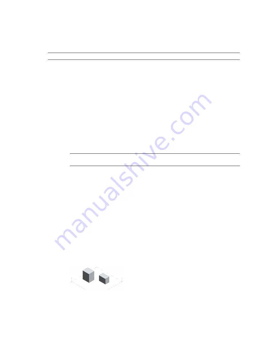
To create a surface using 3D snapping
1
on page 551.)
Drawing in the Conceptual Design Environment | 533
Summary of Contents for 256B1-05A761-1301 - AutoCAD Revit Structure Suite 2010
Page 1: ...Revit Architecture 2010 User s Guide March 2009 ...
Page 4: ......
Page 42: ...xlii ...
Page 84: ...42 ...
Page 126: ...84 ...
Page 166: ...124 ...
Page 229: ...Schedule Field Formatting Calculating Totals Specifying Schedule Properties 187 ...
Page 230: ...Schedule with Grid Lines Schedule with Grid Lines and an Outline 188 Chapter 5 Project Views ...
Page 304: ...262 ...
Page 427: ...Defining the first scale vector Defining the second scale vector Resizing Graphically 385 ...
Page 454: ...Before painting applying material to stairs 412 Chapter 8 Editing Elements ...
Page 456: ...414 ...
Page 486: ...444 ...
Page 674: ...632 ...
Page 809: ...Curtain wall Curtain Grid Curtain Walls Curtain Grids and Mullions 767 ...
Page 994: ...952 ...
Page 1016: ...974 ...
Page 1204: ...1162 ...
Page 1290: ...1248 ...
Page 1318: ...1276 ...
Page 1372: ...1330 ...
Page 1382: ...1340 ...
Page 1462: ...1420 ...
Page 1492: ...1450 ...


