


Reorient the View of a Model with the ViewCube
ViewCube is used to reorient the current view of a model. You can reorient the view of a model with the
ViewCube by clicking pre-defined areas to set a preset view current, click and drag to freely change the view
angle of the model, and define and restore the Home view.
Reorient the Current View
The ViewCube provides twenty-six defined areas you can click to change the current view of a model. The
twenty-six defined areas are categorized into three groups: corner, edge, and face. Of the twenty-six defined
areas, six of the areas represent standard orthogonal views of a model: top, bottom, front, back, left, and
right. Orthogonal views are set by clicking one of the faces on the ViewCube.
NOTE
When the cursor is over one of the clickable areas of the ViewCube, the cursor changes to an arrow with
a small cube to indicate the cursor is over the ViewCube. In addition to the cursor changing, a tooltip is also
displayed. The tooltip describes the action that can be performed based on the location of the cursor over the
ViewCube.
You use the other twenty defined areas to access angled views of a model. Clicking one of the corners on
the ViewCube reorients the current view of the model to a three-quarter view, based on a viewpoint defined
by three sides of the model. Clicking one of the edges reorients the view of the model to a half view based
on two sides of the model.
You can also click and drag the ViewCube to reorient the view of a model to a custom viewpoint other than
one of the twenty-six predefined viewpoints that are available. As you drag, the mouse pointer changes to
indicate that you are reorienting the current view of the model. If you drag the ViewCube close to one of
the preset orientations and it is set to snap to the closest view, the ViewCube rotates to the closest preset
orientation.
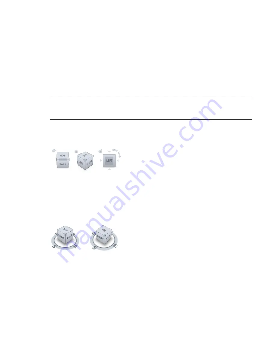
The outline of the ViewCube helps you identify the view orientation. When a view is oriented to one of the
twenty-six pre-defined ViewCube orientations, the ViewCube is outlined in a solid continuous line. When
a view is not constrained to one of the twenty-six pre-defined orientations, its outline is displayed as dashed.
Pre-defined orientation left, free-form
orientation right.
Roll a Face View
When you view a model from one of the face views, two roll arrow buttons are displayed near the ViewCube.
Use the roll arrows to rotate the current view 90 degrees clockwise or counterclockwise around the center
of the view.
220 | Chapter 5 Project Views
Summary of Contents for 256B1-05A761-1301 - AutoCAD Revit Structure Suite 2010
Page 1: ...Revit Architecture 2010 User s Guide March 2009 ...
Page 4: ......
Page 42: ...xlii ...
Page 84: ...42 ...
Page 126: ...84 ...
Page 166: ...124 ...
Page 229: ...Schedule Field Formatting Calculating Totals Specifying Schedule Properties 187 ...
Page 230: ...Schedule with Grid Lines Schedule with Grid Lines and an Outline 188 Chapter 5 Project Views ...
Page 304: ...262 ...
Page 427: ...Defining the first scale vector Defining the second scale vector Resizing Graphically 385 ...
Page 454: ...Before painting applying material to stairs 412 Chapter 8 Editing Elements ...
Page 456: ...414 ...
Page 486: ...444 ...
Page 674: ...632 ...
Page 809: ...Curtain wall Curtain Grid Curtain Walls Curtain Grids and Mullions 767 ...
Page 994: ...952 ...
Page 1016: ...974 ...
Page 1204: ...1162 ...
Page 1290: ...1248 ...
Page 1318: ...1276 ...
Page 1372: ...1330 ...
Page 1382: ...1340 ...
Page 1462: ...1420 ...
Page 1492: ...1450 ...


