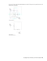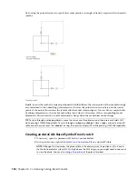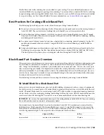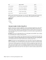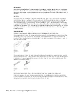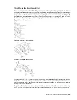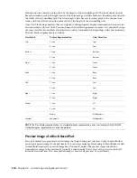
in the…
aligns with the…
The…
XY plane.
bottom side of the model block
bottom view block
XZ plane.
front side of the model block
front view block
XZ plane.
back side of the model block
back view block
YZ plane.
left side of the model block
left view block
YZ plane.
right side of the model block
right view block
NOTE
To ensure correct display control of part sizes when a part is added to your drawings, draw geometry for
the model block on layer 0, assign BYBLOCK for color and linetype, and assign BYLAYER for lineweight.
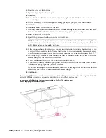
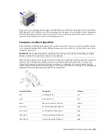
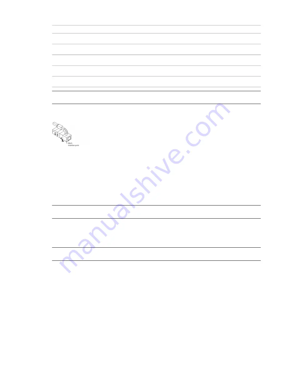
Sample 3D model
block of an air
handling unit
Schematic Symbol of a Block-Based Part
Generally, every part has a schematic symbol that you add to your schematic design layouts. Using Content
Builder, you can assign each part a symbol block. You can assign a different symbol to each part size, or
assign the same symbol to all part sizes. The symbol block provides a schematic representation of the part
size for use in plan views. Typically, the same symbol block is used for all the part sizes in a part family. You
must save the symbol block in an AutoCAD
®
drawing file. You can save one or more symbol blocks in the
same drawing file.
IMPORTANT
Do not save the symbol block drawings in the catalog folders of AutoCAD MEP. These are working
files and should be saved in a separate, or temporary, folder.
You can use any drawing command to create the geometry for the blocks. Standard AutoCAD entities such
as lines, polylines, or circles are recommended. Once the schematic symbol block is created, Content Builder
scales and wraps the symbol block with a bounding box of the 3D model. This ensures that valid connections
can be maintained between the schematic symbol and the connecting schematic lines.
WARNING
Be careful when using AEC-based geometry, such as walls or ducts, to create your symbol. To avoid
object enabler problems, be sure to explode the geometry to base AutoCAD entities before running MvPart Builder.
To ensure correct display control of your symbol when it is added to your drawings, draw geometry for the
symbol on layer 0, assign BYBLOCK for color and linetype, and assign BYLAYER for lineweight. The insertion
point, or base point, is used as a reference for positioning the block upon insertion. The insertion point for
the schematic block should be the same as the 3D model block that it represents. When you place the MvPart
in a drawing, all associated blocks are part of one object; therefore, you want to maintain a common insertion
point.
746 | Chapter 14 Customizing Catalog-Based Content
Summary of Contents for 235B1-05A761-1301 - AutoCAD MEP 2010
Page 1: ...AutoCAD MEP 2010 User s Guide March 2009 ...
Page 22: ...4 ...
Page 86: ...68 ...
Page 146: ...128 ...
Page 180: ...162 ...
Page 242: ...Modifying the elevation of a duct 224 Chapter 6 Drawing HVAC Systems ...
Page 264: ...246 ...
Page 480: ...462 ...
Page 534: ...516 ...
Page 616: ...598 ...
Page 658: ...640 ...
Page 788: ...770 ...
Page 802: ...784 ...
Page 820: ...802 ...
Page 878: ...860 ...

