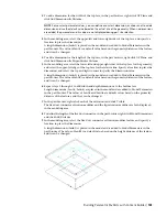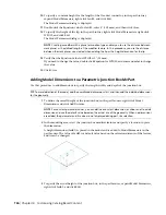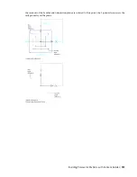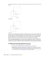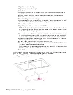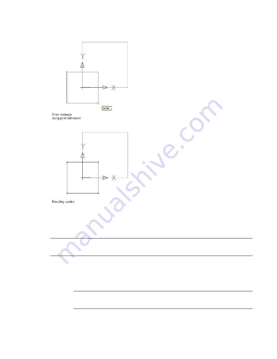
Next, using the point references to specify the corner points, a rectangle is drawn to represent the schematic
symbol.
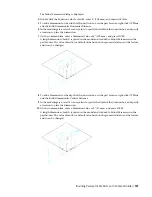
Finally, to cause the symbol to scale proportionally with the diffuser, the corner points of the symbol rectangle
are constrained to the underlying point references. Because the point references are based on the corner
points of the model, this ensures the symbol and the model remain aligned. You can also accomplish this
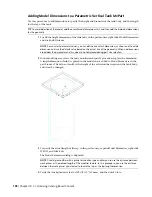
by adding dimensions to the symbol and setting their values to the names of the corresponding model
dimensions. This ensures the symbol dimensions change when the model dimensions change.
TIP
To cycle through overlapping objects, move the cursor over the object on top, then press and hold SHIFT
while pressing SPACEBAR repeatedly. To cycle through overlapping subobjects (faces, edges, and vertices) on 3D
solids, move the cursor over the subobject on top, then press and hold CTRL while pressing SPACEBAR repeatedly.
Creating an AutoCAD-Based Symbol from Scratch
1
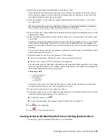
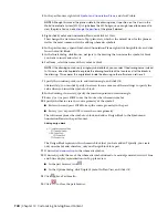
If necessary, open the parametric MvPart in Content Builder.
2
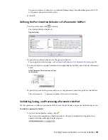
In the part browser, right-click
, and click Visible.
NOTE
Although this step makes the plane visible in the drawing area, its position on the Z axis in
the World Coordinate System (WCS) is high above the WCS origin, so you might need to zoom out
to view the plane. You can also
738 | Chapter 14 Customizing Catalog-Based Content
Summary of Contents for 235B1-05A761-1301 - AutoCAD MEP 2010
Page 1: ...AutoCAD MEP 2010 User s Guide March 2009 ...
Page 22: ...4 ...
Page 86: ...68 ...
Page 146: ...128 ...
Page 180: ...162 ...
Page 242: ...Modifying the elevation of a duct 224 Chapter 6 Drawing HVAC Systems ...
Page 264: ...246 ...
Page 480: ...462 ...
Page 534: ...516 ...
Page 616: ...598 ...
Page 658: ...640 ...
Page 788: ...770 ...
Page 802: ...784 ...
Page 820: ...802 ...
Page 878: ...860 ...


