


Model of a Parametric Part
A model is the graphical representation of a parametric part. In Content Builder, a model consists of various
features that have specific relationships to each other and that define the behavior of the parametric part.
Some features require that you create simple shapes or points, while others require an extrusion or path.
Some represent visible geometry, and some help you to position geometry precisely on a part. You can
modify features to refine and improve your parts over time. You change features by modifying their size
and shape or by flipping or moving them. To effectively model a parametric part, it is important to understand
how each feature relates to the other features of modeling.
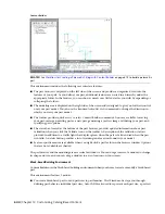
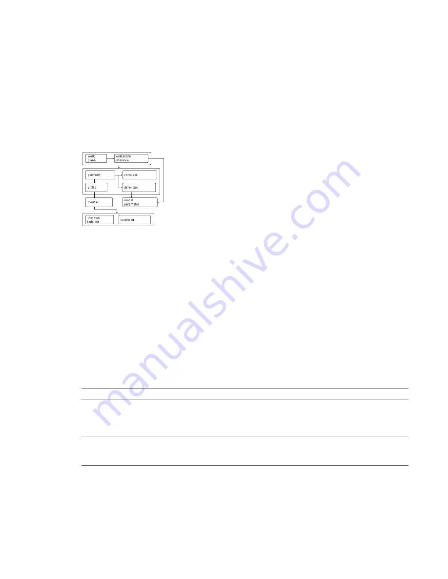
The following illustration shows the features that make up the model. Arrows indicate the direction of the
relationship between features. For example, modifying geometry affects a profile, which affects a modifier,
and so on.
The following sections introduce the features of modeling. Refer to this illustration as you learn more about
each feature to help you understand the relationships between features.
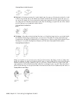
Work Planes
A work plane is a modeling feature that defines the location of a plane in 3-dimensional (3D) space. It is an
infinite construction plane that can be placed at any orientation in space. It can be offset from an existing
work plane, or it can reference 3D geometry. Using a work plane, you define the geometry, dimensions,
constraints, and profiles that make up the part model. Work planes help you to place geometry that would
otherwise be difficult to position parametrically. By constraining geometry to work planes, you can control
their location. Work planes help you to define relationships between features and provide control when
placing features.
A work plane is displayed as a rectangular 2-dimensional (2D) object. The work plane display is only a visual
representation of the infinite plane and cannot be moved or resized. However, you can control its visibility
for ease of viewing the model. Offset and reference work planes are user-defined and provide the flexibility
to be moved and redefined.
NOTE
To ensure a manageable model size, it is recommended to use a minimum number of work planes.
When you right-click on a work plane in the part browser, it is highlighted in the modeling area. You can
change the view direction to match that of the selected work plane when adding geometry or dimensions
by using the Set View option on the Work Plane context menu.
IMPORTANT
Any features attached to a work plane are restricted to the original plane. If you move a work plane,
any features attached to the plane also move. If you delete a work plane, any features attached to the plane are
also deleted. Each feature attached to a work plane appears under the Work Plane folder in the part browser.
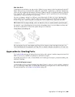
Content Builder provides 3 default work planes that intersect at the origin of the X, Y, and Z axes. The default
work planes help you to get started with modeling a part. You can add work planes at any time during the
modeling process. Each work plane has its own internal coordinate system. Work planes can be created on
any plane in the current user coordinate system (UCS) or in the World Coordinate System (WCS).
654 | Chapter 14 Customizing Catalog-Based Content
Summary of Contents for 235B1-05A761-1301 - AutoCAD MEP 2010
Page 1: ...AutoCAD MEP 2010 User s Guide March 2009 ...
Page 22: ...4 ...
Page 86: ...68 ...
Page 146: ...128 ...
Page 180: ...162 ...
Page 242: ...Modifying the elevation of a duct 224 Chapter 6 Drawing HVAC Systems ...
Page 264: ...246 ...
Page 480: ...462 ...
Page 534: ...516 ...
Page 616: ...598 ...
Page 658: ...640 ...
Page 788: ...770 ...
Page 802: ...784 ...
Page 820: ...802 ...
Page 878: ...860 ...


