


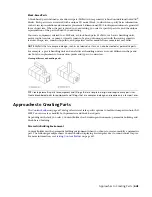


Block-Based Parts
A block-based part is defined as a multi-view part (MvPart) whose geometry is based on individual AutoCAD
®
blocks. Each part size is associated with a unique 3D model block, to which you specify basic information
such as view representations and connector placement. 2-dimensional (2D) block representations are generated
for each part size. When the part is placed in your drawing, you select a specific part size, and the unique
representation of the part is added to your drawing.
You create equipment, referred to as MvParts, as block-based parts. MvParts, such as air handling units,
motor control centers, or pumps, typically consist of a group of unique parts with their own geometric
features. Shape, size, connection points, and properties such as manufacturer or material may differ.
NOTE
MvParts that are simple in design, such as air terminals or fans, can also be created as parametric parts.
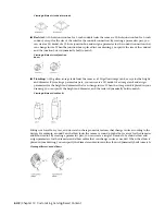
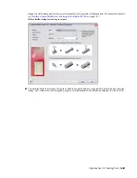
For example, a gas air handling unit and an electric air handling unit are not only different in shape and
size but also in placement of connection points and types of connectors.
Viewing different air handling units
TIP
Create parametric parts for equipment and fittings that are simple in design and require many part sizes.
Create block-based parts for equipment and fittings that are complex in design and require only a few part sizes.
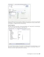
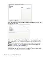
Approaches to Creating Parts
on page 647 dialog offers several task-specific options to build custom parts in AutoCAD
MEP. You can create or modify both parametric and block-based parts.
Depending on the task you select, Content Builder has 2 working environments: parametric building and
block-based building.
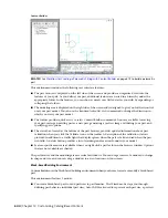
Parametric Building Environment
Content Builder uses the parametric building environment when you choose to create or modify a parametric
part. The following example shows Content Builder displaying a rectangular duct to round conical tap tee.
For more information, see
on page 647.
Approaches to Creating Parts | 643
Summary of Contents for 235B1-05A761-1301 - AutoCAD MEP 2010
Page 1: ...AutoCAD MEP 2010 User s Guide March 2009 ...
Page 22: ...4 ...
Page 86: ...68 ...
Page 146: ...128 ...
Page 180: ...162 ...
Page 242: ...Modifying the elevation of a duct 224 Chapter 6 Drawing HVAC Systems ...
Page 264: ...246 ...
Page 480: ...462 ...
Page 534: ...516 ...
Page 616: ...598 ...
Page 658: ...640 ...
Page 788: ...770 ...
Page 802: ...784 ...
Page 820: ...802 ...
Page 878: ...860 ...


