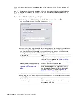
then…
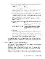
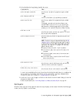
If you want to…
in the Select File dialog, select the drawing, click Save, and then
click Yes to confirm that the contents of the drawing can be
overwritten.
overwrite the contents of an existing draw-
ing
4
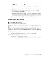
Click Generate.
The software creates the schematic symbol styles using the conversion script and the block
definitions from the referenced drawings.
IMPORTANT
If you need to make a few changes to the new styles, modify the symbol conversion
script and repeat the conversion process to apply the changes. If you make the changes using the
Style Manager instead, the changes are overwritten if you subsequently repeat the conversion process.
5
If there are errors in the process, click Log to view them. Otherwise, click Close.
Creating Symbol Conversion Scripts
A symbol conversion script in a CCF file contains the following information:
■
values for schematic symbol style settings
■
references to drawings that contain AutoCAD
®
blocks
The software uses both the script and the blocks to create the schematic symbol styles and their associated
views.
If you are creating a set of schematic symbol styles using the blocks in your existing block libraries, you need
to create a conversion script. If you are customizing a set of existing styles, you already have a script as a
result of the conversion of the existing styles to their individual components, and you can modify that script
instead.
To create a symbol conversion script
1
Click Manage tab
➤
MEP Content panel
➤
➤
Batch Convert Symbols
.
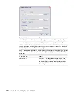
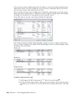
The software displays the Batch Convert Symbols dialog.
2
In the Batch Convert Symbols dialog, click Create.
3
In the Symbol Conversion Script dialog, under Convert, specify the file or files that contain the
blocks to convert to schematic symbol styles:
Converting Blocks to Schematic Symbol Styles | 633
Summary of Contents for 235B1-05A761-1301 - AutoCAD MEP 2010
Page 1: ...AutoCAD MEP 2010 User s Guide March 2009 ...
Page 22: ...4 ...
Page 86: ...68 ...
Page 146: ...128 ...
Page 180: ...162 ...
Page 242: ...Modifying the elevation of a duct 224 Chapter 6 Drawing HVAC Systems ...
Page 264: ...246 ...
Page 480: ...462 ...
Page 534: ...516 ...
Page 616: ...598 ...
Page 658: ...640 ...
Page 788: ...770 ...
Page 802: ...784 ...
Page 820: ...802 ...
Page 878: ...860 ...


