


4
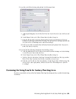
In the Size Sanitary Plumbing Line dialog, under Design Values, select the plumbing line sizing
table definition that you created based on applicable codes, such as the Uniform Plumbing Code.
The software uses the table definition to determine the maximum permissible fixture unit loads
for the type of run that you specify in the next step.
TIP
To examine the table definition in order to verify its accuracy, click the Plumbing Line Sizing
Table icon.
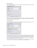
5
Select a type of plumbing line for Base Sizing On. You can base the sizing on a
,
The non-editable sections in the Size Sanitary Plumbing Line dialog contain the results of the
sizing calculations. For more information, see
Reviewing the Sizing Results for Sanitary Plumbing
on page 513.
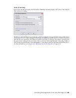
6
Click OK to resize the system.
Sizing Sanitary Plumbing Lines for Multiple Floors
Most sanitary systems are found in buildings that contain multiple floors, and each floor of the building is
typically represented in a separate drawing. When sizing a sanitary system that spans multiple floors, you
must size the plumbing lines for each drawing separately, starting from the highest floor and working
downward. You can then reference the individual calculation values from the higher floors as you perform
sizing on the lower floors.
To calculate a sanitary system in a 3-story building
1
Open the third-floor drawing and perform the following actions:
a
Click the plumbing line closest to the second floor riser to select the run to size for the
third floor.
b
Under Design Values, verify that Branch is selected for Base Sizing On.
c
Make a note of the calculated value for Fixture Units Upstream. You need to know this
value for the subsequent steps.
512 | Chapter 10 Drawing Plumbing Systems
Summary of Contents for 235B1-05A761-1301 - AutoCAD MEP 2010
Page 1: ...AutoCAD MEP 2010 User s Guide March 2009 ...
Page 22: ...4 ...
Page 86: ...68 ...
Page 146: ...128 ...
Page 180: ...162 ...
Page 242: ...Modifying the elevation of a duct 224 Chapter 6 Drawing HVAC Systems ...
Page 264: ...246 ...
Page 480: ...462 ...
Page 534: ...516 ...
Page 616: ...598 ...
Page 658: ...640 ...
Page 788: ...770 ...
Page 802: ...784 ...
Page 820: ...802 ...
Page 878: ...860 ...


