background image

5

Click ESC to save your changes and exit.

Connecting Plumbing Lines at Different Elevations

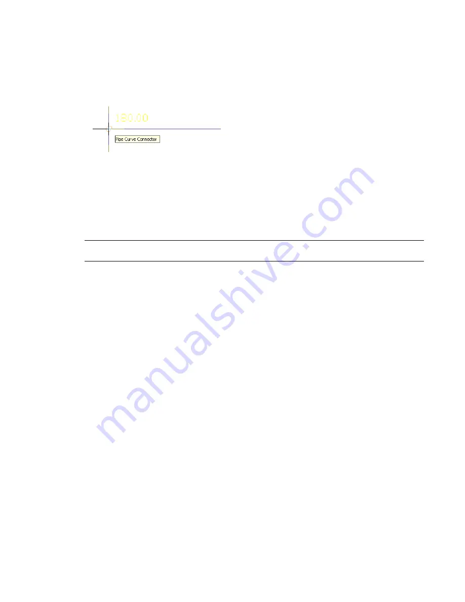
As you draw a plumbing system, sometimes you need to start or end a run by connecting (snapping) to the
endpoint of an existing plumbing line, or to a point along its curve.

If the connecting plumbing line has a different elevation than the one you are starting or ending, you are
prompted to decide how to connect the 2 plumbing lines:

Add a riser to the connecting plumbing line

If you are connecting to an end connector, the software inserts a drop symbol to represent the change in
elevation. If you are connecting to a point on the curve of the plumbing line, the software inserts the tee
specified as the default fitting for Tee Up or for Tee Down in the plumbing system definition, depending
on the elevation of the 2 lines.

RELATED

For more information on specifying default fittings, see 

Specifying the Default Fittings for a Plumbing

System Definition

 on page 478.

Add a riser to the fixture

If you are connecting from a fixture to a plumbing line, the software adds a riser to the fixture (MvPart),
rather than to the end of the connecting line.

Adjust the slope

The slope of the plumbing line that you are starting or ending is adjusted based on the difference in elevation.
If you are connecting to an end connector, an elbow is inserted. If you are connecting to a point on the
curve of the plumbing line, a tee is inserted.

Adjust the connecting plumbing line elevation

The elevation of the plumbing line you are starting or ending is changed to match the elevation of the
plumbing line to which you are connecting. If you are connecting to an end connector, an elbow is inserted.
If you are connecting to a point on the curve of the plumbing line, a tee is inserted.

Do Not Make a Connection

Avoid making the connection.

Overriding the Default Plumbing Fittings for an Individual Run

Before you draw a plumbing run, you specify a system. As you draw the run, the software inserts plumbing
fittings based on the 

default fittings

 configured in that system definition.

Generally, this insertion behavior for fittings is desirable because all of the runs in a plumbing system
typically have the same types of fittings. For example, a sanitary waste system typically has runs with sanitary
tee fittings. However, you can override the default fittings for an individual run that you are drawing. This
enables the run to have a unique set of fittings regardless of the system.

Connecting Plumbing Lines at Different Elevations | 489

Summary of Contents for 235B1-05A761-1301 - AutoCAD MEP 2010

Page 1: ...AutoCAD MEP 2010 User s Guide March 2009 ...

Page 2: ...ers MPI MPI design logo Moldflow Plastics Insight MPX MPX design logo Moldflow Plastics Xpert Third Party Software Program Credits ACIS Copyright 1989 2001 Spatial Corp Portions Copyright 2002 Autodesk Inc Flash is a registered trademark of Macromedia Inc in the United States and or other countries International CorrectSpell Spelling Correction System 1995 by Lernout Hauspie Speech Products N V Al...

Page 3: ...m AutoCAD to AutoCAD MEP 5 AutoCAD to AutoCAD MEP Task Comparisons 5 Creating Building Systems 6 AutoCAD MEP Workspaces 6 Insertion Tools 7 Layer Keying 7 Modifying Building Systems 7 Associative Movement 7 Grips 8 Snaps 11 Automating Design Tasks 12 Domain Specific Ribbons 12 Auto Layout 12 Interference Detection 12 Connectivity Checks 13 Working With Sizing and Calculation Tools 13 Sizing Tools ...

Page 4: ... 27 About AutoCAD MEP 27 AutoCAD MEP Workflow 28 Intelligent Objects 28 Location of Part Catalogs 29 Analysis Tools 30 Project Management Tools 30 Contacting Autodesk 30 Getting Help 31 Guides 31 Tutorials 32 Training 32 Classes 32 Courseware 32 E Learning 32 Certification 33 Discussion Groups 33 Additional Resources 33 Updating AutoCAD MEP 33 The AutoCAD MEP 2010 Drawing Domain 33 Workspace Funda...

Page 5: ...og and Palette Tooltips 61 Object Rollover Tooltips 62 Property Palette Tooltips 62 Thumbnail Preview Tooltips 63 Solution Tips 64 Object Grip Tooltips 65 Working in Model Space and Paper Space 66 Customizing the Display of MEP Objects 66 Using Custom Display 67 Chapter 4 Drawing Essentials 69 Drawing Preferences 69 About Layout Preferences 69 Initialization Preferences 70 Specifying Part Catalogs...

Page 6: ...cting a Display Configuration 102 Essentials of Objects 103 Object Types 104 Matching Object Properties 106 Working with Connectors 107 Working with Anchors 108 Attaching Objects with a Curve Anchor 109 Attaching Objects with a System Anchor 110 Attaching Objects with a Reference Anchor 110 Rotating Objects Attached with Curve Anchors 110 Releasing Anchored Objects 111 Part Anchors 111 Using the C...

Page 7: ...ing Hidden Lines for Objects 152 Display of Center Lines on Ducts 152 Display of Objects by Classification 154 Adding Custom Graphics as a Display Component 155 Troubleshooting Object Display 155 AutoCAD MEP Templates 156 Default Drawing Templates 156 Creating a Custom Template from a Template or Drawing 157 Creating a Custom Template 158 Working with Referenced Drawings 158 Attaching or Overlayin...

Page 8: ...t Run 201 Drawing 1 Line Duct 201 Calculating Duct Sizes for a Duct System 203 Adding a Duct Fitting Manually 205 Drawing Flexible Duct 206 Adding a Parallel Duct Run 207 Offsetting Duct from Existing Geometry 208 Drawing Sloped Duct 208 Using the Elevation Lock 208 Connecting Ducts Through Referenced Drawings 209 Adding a Takeoff to a Duct 211 Converting a Line to Duct 213 Converting a Polyline t...

Page 9: ...orkflow for Designing a Pipe System 247 Associative Movement 248 Movement of a Pipe Segment 248 Movement of a Pipe MvPart 249 Routing Preferences 250 Auto Layout 252 Routing Solutions 254 Sloped Piping 256 Pipe System Definitions 257 Pipe System Displays 258 Display Configurations in AutoCAD MEP 258 1 Line Display 259 Graphical 1 Line Display 260 2 Line Display 260 Straight Centerline Display of E...

Page 10: ...lation to Pipe 317 Adding Labels or Flow Arrows to Pipe 317 Converting a Polyline to Flexible Pipe 318 Modifying a Piping System 318 Selecting or Filtering Objects 318 Filtering Pipe Objects with Quick Select 319 Filtering by Pipe Part Type 319 Modifying Components Using Grips 320 Moving Pipe Components Using Location Grips 320 Modifying the Elevation of Pipe Components 320 Rotating Pipe Component...

Page 11: ...t 354 Circuits 356 Electrical Project Database 356 Circuit Manager 356 Electrical Objects 357 Devices 357 Panels 358 Wires 359 Wire Size Calculations 360 Cable Trays and Conduits 360 Auto Layout 361 Cable Tray and Conduit Settings 361 Electrical and Wire Ways Snaps 361 Customizable Electrical Content 362 Control the Appearance and Behavior of Electrical System Designs 363 Creating Electrical Syste...

Page 12: ...of Devices 401 Example Inserting a Device into a Wire 403 Adding Panels 403 Example Aligning a Panel to Floor Plan Geometry 409 Copying Devices and Panels 409 Example Copying a Device 411 Example Copying a Panel 412 Adding Wires 412 Drawing or Generating Wires 413 Drawing a Home Run 418 Creating a Wire from a Polyline 419 Adding Electrical Equipment 419 Drawing Cable Trays and Conduits 420 Drawing...

Page 13: ...Plumbing Line Segment 466 Movement of an MvPart 467 Plumbing Grips 469 Grips for Adding to a Plumbing Run 469 Grips for Modifying a Plumbing Run 470 Rise Run Angles and Slope 475 Fixture Units 475 Calculations 475 Plumbing Line Sizing Tables 475 Customizing Plumbing Content 477 Creating Style Based Content 477 Creating Catalog Based Content 477 Configuring Plumbing System Definitions 477 Creating ...

Page 14: ...wing the Sizing Results for Supply Plumbing Lines 503 Calculations for the Longest Run 503 Calculations at Selected Component 504 How the Software Performs Calculations to Size Plumbing Lines 507 Calculating the Sizes of Sanitary Plumbing Lines 508 Overview of Sizing Sanitary Plumbing Lines 508 Sanitary Branch Sizing 509 Sanitary Offset Sizing 510 Sanitary Stack Sizing 511 Sizing Sanitary Plumbing...

Page 15: ...Tags and Schedules 564 Schedules 566 Adding a Schedule 566 Linking a Schedule to an External Drawing 567 Creating an Electrical Panel Schedule 567 Updating a Schedule 567 Exporting a Schedule to a Spreadsheet 568 Views 568 Creating a General View 568 Creating a Detail View 569 Creating a Section View 570 Creating an Elevation View 573 Updating a Section or Elevation View 575 Sheets 576 Creating a ...

Page 16: ...g Rise Drop Styles 614 Connector Styles 616 Categorizing Style Based Content 617 Creating Categories in AutoCAD MEP 617 Customizing Device Content 618 Converting Blocks and Parts to Devices 618 Converting Device Styles to Blocks 620 Converting Blocks to Device Styles 622 Creating Device Conversion Scripts 623 Modifying Device Conversion Scripts 625 Customizing Schematic Symbol Content 630 Converti...

Page 17: ...tors of a Block Based Part 751 Property Set Information for a Block Based Part 752 Workflow for Creating a Block Based Part 753 Creating Block Based Parts Using Content Builder 754 Creating a 3D Model and Schematic Symbol for a Block Based MvPart 754 Starting Content Builder for Creating a Block Based MvPart 757 Defining the Part Behavior of a Block Based MvPart 757 Assigning Part Size Names and V...

Page 18: ...ifying Different Tool Palettes for the Tool Palette Set 789 Renaming the Tool Palette Set 789 Customizing Tools 789 Creating Tools for Style Based Content 790 Creating Tools from Routing Preferences 792 Creating Tools from AEC Content in DesignCenter 792 Creating Command Tools 793 Creating Property Based Tools 794 Changing Tool Properties 795 Changing Tool Icons 795 Deleting Tools 796 Chapter 17 W...

Page 19: ...ormation see Workspace Components on page 38 New Features for Drawing Electrical Systems Panel Schedule Enhancements As you design and refine electrical systems a graphical representation shows that an electrical panel schedule is out of date Adding or changing circuits and panels plus certain other operations require that panel schedules be refreshed Use the Regen command to update the schedule F...

Page 20: ...ences on page 293 Angle of deflection also called fitting tolerance specifies whether to allow deflection at joints with a tolerance angle and includes female connection types with non standard angles based on manufacturer requirements To enable angle of deflection as you add pipe select Yes for the Use fitting tolerance option on the Pipe Properties palette For more information see Angle of Defle...

Page 21: ... objects based on elevation You can differentiate the display attributes for these parts relative to their location above or below the active cut plane and display ranges For more information see Display of Objects Based on Elevation on page 144 New Features for Building Systems Converting Solids or Mass Elements to Block Based Parts Convert 3D solids or mass elements directly to block based MvPar...

Page 22: ...4 ...

Page 23: ...project standards and deviations yes yes Edit geometric elements such as lines polylines arcs and circles yes yes Import or export data in DWG DWF IFC and other formats yes no Import or export engineering data in the Green Building Extensible Markup Lan guage gbXML format for analysis by third party tools yes yes Adjust annotation on page 17 style and scaling yes no Use the AutoCAD MEP workspaces ...

Page 24: ...fine your designs For example you can create a duct system on page 194 that contains ceiling diffusers with a specified flow rate The system can detect the amount of downstream airflow required by the diffusers You can use sloped piping on page 256 to design gravity based piping system You can use circuit features on page 380 to create and manage circuits for your electrical plans You can place pl...

Page 25: ...ou add parts to your layouts each object is automatically placed on the correct layer With layer keying AutoCAD MEP automatically places an object on a predefined layer that conforms to a particular layer standard You can modify the layer standards to map to specific company standards You can also turn layers on or off for a particular system or use filters to disable objects on a particular layer...

Page 26: ...ake direct changes to a part segment in a drawing Hovering over a grip displays a tooltip describing the grip s function Some tooltips also suggest options such as using the CTRL or ALT keys For more information see Designing with Dynamic Input and Grips on page 114 Several types of grips are available Add grips add segments such as duct pipe plumbing line wire cable tray or conduit to a new or ex...

Page 27: ... grips move a component in the current XY plane Location grips appear at the insertion and connector points on a part Plumbing MvPart Lengthen grips change the length of a part segment Lengthen grips use the segment s current orientation to maintain connectivity in the existing run Grips 9 ...

Page 28: ...on flipped Diamond shaped rotate grips in isometric views rotate an object around its centerline to any angle if that object has round connectors on opposite ends Rotate grips are available on parts and fittings that can be rotated without breaking the connection with existing objects Rotating a damper in an isometric view 10 Chapter 2 Moving from AutoCAD to AutoCAD MEP ...

Page 29: ...y to a pipe end connector at the end of a pipe segment AutoCAD MEP snaps are available in all the engineering workspaces For more information see Configuring AutoCAD MEP Snaps on page 75 Segments such as duct and pipe contain end connector snaps and curve connector snaps End connector snaps connect new objects to the ends of existing objects Curve connector snaps connect a segment anywhere along t...

Page 30: ...configurations System definition settings control the appearance and functions of parts in a system You can also override system settings to accommodate unique part requirements For more information see Workspace Components on page 38 Auto Layout Auto layout can generate routing solutions that you can use as you lay out duct pipe cable tray or conduit runs AutoCAD MEP automatically inserts the app...

Page 31: ... that are connected to a particular object The software verifies that adjacent parts are properly connected and that connectivity is continuous throughout the run or branches In the Electrical workspace the Show Connected Objects command checks the connectivity between the lighting devices wires junction boxes and switches in a lighting network as well as between MvParts and conduit or cable tray ...

Page 32: ...es Sanitary plumbing line sizing tables specify the maximum allowable fixture unit loads for different types of sanitary runs stacks branches and offsets You can also customize the sizing tables to meet your project requirements or conform to applicable codes You can also use the plumbing line slope tool to compute the start elevation end elevation or slope of a plumbing line based on the starting...

Page 33: ...iginal drawing or to automate the creation of section views As the design changes manually updating section views is not only time consuming but also error prone You also would need to use a text editor in AutoCAD to perform tasks such as adding labels to objects formatting text justifying positioning or setting scale representations In AutoCAD MEP you can maximize your productivity using automate...

Page 34: ...cause you view AutoCAD MEP systems in 3 dimensions you can also create elevation and detail views For more information see Creating a Section View on page 570 Tagging AutoCAD MEP automates part tagging For example as you create a building system you can add part number tags to objects in the drawing 16 Chapter 2 Moving from AutoCAD to AutoCAD MEP ...

Page 35: ...wing reflect the tagged data For more information see Defining Property Set Data on page 588 and Tags on page 561 Labeling and Annotation Scaling AutoCAD MEP lets you add labels and flow arrows as you lay out a run You can specify the number of labels or flow arrows and the placement of the annotation As you make changes the labeling updates automatically Labeling and Annotation Scaling 17 ...

Page 36: ...ection of vertical segments in the layout for any predefined orthographic view top bottom left right front or back You can display objects differently based on elevation on page 144 You can also change the appearance of hidden lines layers line types or color for crossing or overlapping objects at different elevations in 2 line plan views For example AutoCAD MEP displays hidden lines as dashes as ...

Page 37: ...t Device schedule Because schedules built in AutoCAD MEP are linked any changes additions or deletions to the existing tagging data or part specifications are automatically updated in the schedule The schedule format inherits the schedule table style assigned to the schedule tool However you can modify the table style to reflect the desired data format Leveraging AutoCAD Knowledge in AutoCAD MEP T...

Page 38: ...an invalid connection in the overall building system To maintain the connectivity of objects use Alignment grips to align devices or panels and use Location or Rotate grips snaps and polar tracking to align other objects The grips enable you to move or rotate objects while optionally maintaining their connections to other objects For more information see the following topics Moving Duct Components...

Page 39: ...d 2 objects until they intersect In AutoCAD MEP CHAMFER only works on AutoCAD objects such as lines polylines and 3D solids It does not work on building systems objects such as schematic lines plumbing lines or duct pipe cable tray or conduit segments To extend and connect these types of objects use FILLET EXTEND or a combination of grips snaps and polar tracking For more information see Create Ch...

Page 40: ... AutoCAD MEP object enabler or who have a version of AutoCAD not supported by the Export to AutoCAD commands WARNING Exploding a building systems object causes the object to permanently lose its connectivity with other objects among other changes For this reason always create a copy of the source drawing and then explode the objects on the copy For more information see Export to AutoCAD on page 59...

Page 41: ...elp JOIN The JOIN command joins similar objects to form a single unbroken object You can also use it to create complete circles and ellipses from arcs and elliptical arcs In AutoCAD MEP JOIN only works on AutoCAD objects such as lines polylines arcs and splines However you can join duct pipe cable tray or conduit segments as well as plumbing lines by merging them You can also connect plumbing line...

Page 42: ... to move a selection set of parts fittings and segments for example a complete duct branch the software moves the objects and if possible connects a suitable object in the selection set such as a tee or takeoff to a segment at the destination When connecting the moved object to the segment the software breaks into the segment and then aligns and orients the object and the selection set However the...

Page 43: ...toCAD MEP you should purge unused building systems objects first and then use the Style Manager to purge unused system definitions For more information see the following topics Purging AutoCAD MEP Objects on page 590 Purging Systems on page 101 Erase Objects in the AutoCAD Help ROTATE and ROTATE3D The ROTATE command rotates an object around a base point The ROTATE3D command rotates an object aroun...

Page 44: ...ty On unconnected segments you can also use the Start or End grips to change both the length and angle of the segment To stretch or change the angle of a schematic line drag a grip point to a new location For more information see the following topics Modifying the Length of Ducts on page 225 Modifying the Length of a Pipe Segment on page 322 Modifying the Length of Cable Tray or Conduit Segments o...

Page 45: ...of drawing objects that represent the real world parts in building systems and that connect intelligently to one another Tools specific to the mechanical electrical and plumbing disciplines such as analysis tools for sizing systems for optimal performance Common design tools that you can use in all 3 disciplines Project management tools that integrate building system designs with architectural bui...

Page 46: ...ng with Referenced Drawings on page 158 Use the schematic tool set in MEP to create concept designs See About Schematic Diagrams on page 518 Create preliminary domain outlines using flow and 1 line diagrams Create Create detailed domain designs using catalog parts and custom content HVAC designs on page 163 Electrical designs Plumbing designs Radiant heating system designs Piping system designs Us...

Page 47: ... you do so the software inserts and adjusts the objects in the run to maintain their connectivity For example it inserts appropriately sized fittings as you lay out duct segments It also inserts an appropriately sized transition fitting if you change the size of a segment The ability of the software to detect the attributes of objects and act accordingly to maintain the connectivity of the system ...

Page 48: ...01 or Calculating the Sizes of Sanitary Plumbing Lines on page 508 Project Management Tools AutoCAD MEP includes tools that formalize and automate the processes related to building model design and documentation a Project Browser Use this tool to create design projects and specify high level project information and settings such as the project number project name and the file locations of the tool...

Page 49: ...e includes conceptual information on all features and step by step instructions on performing end user tasks The information in the guide is also included in the online help AutoCAD MEP 2010 Network Administrator s Guide This guide provides information on how to perform network installations or multi seat stand alone installations AutoCAD MEP 2010 Stand Alone Installation Guide This guide provides...

Page 50: ...year for users at all levels to improve their productivity with Autodesk software The preferred training materials of Autodesk partners these books are also well suited for self paced standalone learning All courseware simulates real world projects with hands on job related exercises Autodesk Official Training Courseware AOTC is developed by Autodesk Autodesk Authorized Training Courseware AATC is...

Page 51: ...ility If you are a member of the Autodesk Subscription program the Communication Center also notifies you of additional product information such as extension availability tips and support information You can set the Communication Center to notify you of updates and other information daily weekly or monthly or you can update on demand For more information see Overview of Communication Center in the...

Page 52: ...ool palettes set Drawing Status Bar Menu The drawing status bar menu has been removed from AutoCAD MEP 2010 Commands formerly found there can now be accessed from the application menu Commands on the old menu Help Access With the removal of the menu bars the commands to access Help features have been moved into the InfoCenter at the top right of the application window Here you can find the online ...

Page 53: ... or blocks to Autodesk Seek to give your partners and customers ready access to your content Workspace Fundamentals Workspaces are user interface configurations that determine the ribbon panels that display in the drawing window For example the workspace determines whether the Tool Palettes window and Command Line window float or dock to specific sides of the application window If you work in a mu...

Page 54: ...gn of electrical systems Ribbon tabs are populated with electrical tools and commands and the electrical Electrical tool palette is displayed Electrical Configured for the design of plumbing systems Ribbon tabs are populated with plumbing tools and commands and the Plumbing tool palette group is displayed Plumbing Configured for the design of schematic diagrams Ribbon tabs are populated with schem...

Page 55: ...orkspace and click Save For more information on workspaces including information on modifying workspaces and the differences between workspaces and profiles see Create Task Based Workspaces in AutoCAD Help Switching Workspaces To activate a workspace select the workspace name from the drop down list on the application status bar Piping workspace selected Workspace Settings Select Workspace Setting...

Page 56: ...struction documents In the following sections each component of the workspace is described in detail Components can be turned off and on for different workspaces depending on your requirements For an interactive guide to the user interface click the Help button in the InfoCenter on the top right of the application window and click User Interface Overview 38 Chapter 3 Getting Started ...

Page 57: ... object Contextual tab for duct objects Displaying the Ribbon To display the ribbon if it is not displayed in your workspace or has been turned off enter ribbon on the command line You can use the button at the right of the tab names to modify the appearance of the ribbon as follows To display only the panel titles of the ribbon tabs click Minimize to Panel Titles at the top right of the ribbon To...

Page 58: ...equently used 5 The expanded panel is displayed when you click the arrow To pin the expanded part of the panel onscreen click To tear of a panel from a static ribbon tab 6 If you want a panel from a static tab to remain in your workspace when you switch to another tab you can tear the panel off its tab and use it as a floating palette To do so move the cursor over the title bar of the panel and th...

Page 59: ...fy click Panels right click on the ribbon and click the panel name to deselect it hide a panel click the tab you want to modify click Panels right click on the ribbon and click the panel name to select it display a panel A check mark next to each tab or panel name indicates that it is currently being displayed on the ribbon Locating Commands in the Workspace The ribbon is intuitive and task relate...

Page 60: ... point in a new drawing Application Menu The application menu has a Search mode where you can enter a full or partial command name and see a list of locations in the user interface where the command can be accessed For more information see Application Menu on page 48 Context Menu Commands that refer to a selected object appear on the contextual tab for that object Commands disappear from the ribbo...

Page 61: ...following static tabs on the ribbon The following sections describe these tabs and the panels they contain Home Tab The Home tab contains the most frequently used commands within the software Basic object and drawing tools can be found here as well as frequently used utilities like modification tools layers and basic annotation Build Contains the basic commands for adding the most commonly used ob...

Page 62: ...components directly into drawings or onto tool palettes Floating View Panel The floating View panel offers access to the commands for Views visual styles and the Zoom and Pan tools This panel is not docked to the ribbon by default so you can access it independently of the current ribbon tab You can dock the floating View panel to the Home tab if desired Insert Tab The Insert tab lets you work with...

Page 63: ... Markup Accesses commands for marking up a drawing for review You can add revision clouds mask blocks wipeouts open the Markup Set Manager and load a markup DWF Annotation Scaling Commands here let you add the current scale to objects display and edit the scale list and add and delete scales for annotative objects Analyze Tab The Analyze tab contains all the commands you need to make engineering c...

Page 64: ...the size of solution tips Windows Contains most of the commands that were on the Windows menu in previous versions Here you can switch between open drawings arrange open windows onscreen lock the workspace windows display and hide the drawing window status bar on page 53 turn items on the drawing window status bar on an off and display the text window Manage Tab On the Manage tab you can find feat...

Page 65: ...fy Add Remove Vanes Duct Fitting Calculate Duct Sizes Set Flow Direction Show Update Flow Insert Equipment Custom Fitting Proper ties Calculate Duct Sizes Set Flow Direc tion Show Update Flow Duct Custom Fitting Insert Equipment Flex Duct Properties Flex Duct Modify Calculate Duct Sizes Set Flow Direction Show Update Flow Duct Flex Insert Equipment Pipe Properties Modify Run Pipe Length Set Flow D...

Page 66: ... Wire Insert Symbol Schematic Line Show Connected Objects Schematic Symbol Dimensions Send To Multiple Objects Zoom to Tags Opening Symbols Edit in Place Interference Application Menu The application menu contains commands that are relevant for the drawing as a whole The application menu contains commands for the following file operations Create new drawings and projects Open drawing files project...

Page 67: ...s Application menu Static ribbon tabs Any contextual tab currently on display Quick Access toolbar You can enter the following strings to search for Display name of the command in application menu ribbon or Quick Access toolbar For example you can enter Style Manager or Plot Preview Part of the display name If you are not sure what the exact name is you can enter a part of the name for example Sty...

Page 68: ...u display click at the right side of the text entry box Displaying Recently Opened Documents in the Application Menu The application menu lets you display a list of recently opened documents according to preferences you specify 1 Click to open the application menu 2 At the top of the menu click Recent Documents 3 At the top of the menu under Recent Documents specify how you want documents grouped ...

Page 69: ... to display file type icons or preview images next to the document names Changing the Number of Recent Files and Actions in the Application Menu Use this procedure to change the default number 9 of recent documents displayed in the application menu 1 Click to open the application menu 2 At the bottom of the application menu click Options 3 On the Open and Save tab of the Options dialog under Appli...

Page 70: ...nd on the Quick Access toolbar right click and click Remove from Quick Access Toolbar Context Menus When you right click in the drawing area the content of the context menu depends on the currently selected object s For example if one or more duct objects are selected a duct specific context menu is displayed as shown Duct context menu Most commands that can be found on the context menu of an obje...

Page 71: ...ation to an object such as classifications notes reference documents hyperlinks and property set data You typically keep the Properties palette open during an AutoCAD MEP session For more information see Working with the Properties Palette on page 91 Drawing Status Bar Located at the bottom of the drawing area the drawing status bar displays status information about the current drawing and provide...

Page 72: ... hatching on or off For more information see Working with Surface Hatches Layer Key Overrides Lets you switch layer key overrides on or off in the Layer Key Overrides dialog For more information see Layer Key Overrides Isolate Objects Lets you hide or display objects you have selected in the drawing AEC Project Standards When a project is loaded click here to synchronize or configure standards for...

Page 73: ... show and clear commands you want to hide Showing and Hiding the Drawing Status Bar The drawing status bar can be turned on and off from the ribbon or from the application status bar on page 56 To show and hide the drawing status bar click View tab Windows panel Drawing Status Bar Command Line You can directly enter commands using the command line window located immediately below the drawing statu...

Page 74: ...these options see Use Precision Tools in the AutoCAD help The following commands and settings are available on the application status bar Cursor coordinate values Controls the coordinate format as either relative or absolute For more information see Overview of Coordinate Entry in the AutoCAD help Snap Lets you restrict the movement of the cursor to the drawing grid Grid Lets you display a rectang...

Page 75: ...with their model space and layouts Click on the preview image to display the drawing or layout For more information see Quick View Tools and Navigate Between Open Drawings in the AutoCAD Help ShowMotion Provides an onscreen display that can be used to create select and play back cinematic camera animations called shots These animations can be used for presentation purposes or for navigation For mo...

Page 76: ...nu 1 At the right end of the application status bar click the application status bar menu arrow 2 Select commands as desired NOTE Alternatively you can click View tab Windows panel Status Bar to access these commands Project Navigator Palette The Project Navigator palette is the central location to create modify and access AutoCAD MEP project files You typically have the Project Navigator palette ...

Page 77: ... the Favorites panel to access saved topics When you enter keywords or type a phrase and then press ENTER or click the Search button you search multiple Help resources in addition to any files that have been specified in the InfoCenter Settings dialog The results are displayed as links on a panel You can click any of these links to display the Help topic article or document In addition Communicati...

Page 78: ...ands and dialogs you can access a context related Help topic using one of the following methods Press F1 while a command is active or a dialog is open Press F1 while a ribbon tooltip is displayed Click the Help button in a dialog Tooltips In addition to interactive tooltips that help you to create and edit objects see Direct Editing with Grips and Dynamic Dimensions AutoCAD MEP provides tooltips t...

Page 79: ...3 Under Window Elements select Show Tooltips 4 If you want to change the time interval between displaying the basic tooltip and the extended tooltip select a different value for Number of seconds to delay If you want to turn off the extended tooltip information completely deselect Show extended Tooltips Dialog and Palette Tooltips The following dialogs and palettes support extended tooltips Projec...

Page 80: ... for AutoCAD objects such as lines or polylines this information is standardized and cannot be changed For information on how to configure rollover tooltips for AutoCAD objects see Customize Rollover Tooltips in the AutoCAD Customization Guide Property Palette Tooltips The Properties palette displays tooltips when you pause the cursor over a property in the list 62 Chapter 3 Getting Started ...

Page 81: ...detail or a combination of both Displaying thumbnails can be helpful when you are navigating large projects with many drawings To activate preview tooltips in Project Navigator 1 On the Quick Access toolbar click Project Navigator 2 Open the Constructs Views or Sheets tab 3 Right click in the toolbar area at the bottom of the tab Tooltips 63 ...

Page 82: ...can specify the preview size Small Medium or Large Preview Details 5 If you want to display the information provided with the preview and detail tooltips right click and click Preview Details Pane This option displays either a text description or a preview of a selected graphic in an area below the file tree Solution Tips The intended interaction among objects in an AutoCAD MEP drawing depends on ...

Page 83: ...tive action You may be advised to modify the location or the geometry of the object but it is essentially a trial and error approach The messages are tips rather than guaranteed solutions By default solution tip icons are displayed when you are drafting but not during plotting or publishing You can change these settings in the Options dialog using the following procedure 1 Click Options 2 In the O...

Page 84: ...ings and performing other tasks better suited to an isometric view You can create a copy to add a second work tab or delete the work tab if it is not needed for a particular project Sheet Tabs These tabs also called layout tabs are available on the sheet templates Use the tabs to configure a layout of your drawing for plotting or printing The sheet tabs include a border and title block which you c...

Page 85: ...ed NOTE You can change the brightness of the dimming that appears during a Custom Display mode session Click Options Display tab Under Fade Control for In place edit and annotative representations enter a value or drag the slider then click OK After making changes you can save the changes and exit the Custom Display session Alternatively you can discard the changes before exiting to revert to the ...

Page 86: ...68 ...

Page 87: ...ou become more familiar with the software you can experiment with different settings until you create the drawing environment that best suits your needs About Layout Preferences Layout preferences are based on specific drafting or design requirements Typically you apply them to a specific mechanical electrical system and change them as needed to achieve the desired design Examples include settings...

Page 88: ...settings for default part catalogs building elevations drawing layout behavior and tooltip displays Specifying Part Catalogs and Style Based Content Locations 1 Click Options 2 In the Options dialog click the MEP Catalogs tab 3 Under Catalogs expand a domain specific category for example duct and specify the catalogs you want available during layout Part catalogs have an APC Autodesk Part Catalog ...

Page 89: ...gs to the appropriate locations in your new installation where new versions of the catalogs provided with the software are located In the Options dialog you specify the locations of the content part catalogs and style based content you need available during layout If the content is stored on your computer you specify local locations in the dialog If it is stored on a network because it is shared b...

Page 90: ... Rules 1 Click Options 2 In the Options dialog click the MEP Layout Rules tab 3 Under Connection Test Mismatch select a rule Then If you want to select Do not make connection NOTE If you select this option when you are connecting devices with wires and the system of the wire does not match the system of the electrical connector on the device you cannot add the wire draw the part to the selected po...

Page 91: ...elbow with the custom angle can be automatically created in your layout If you use custom sizes any custom parts created are available only in the current drawing and are not saved to the part catalogs for future use If your designs require custom sizes on a regular basis see Customizing Catalog Based Content on page 641 Configuring Part Selection 1 Click Options 2 In the Options dialog click the ...

Page 92: ...of 12 0 create an elevation of 12 0 with the name Supply 1st Floor You can select this elevation when adding duct in the drawing All non vertical duct segments and fittings in the run are automatically placed at 12 0 Configuring Tooltip Settings Tooltips are displayed when you hover the cursor over items such as menus icons or palettes AutoCAD MEP tooltips provide a quick view of object informatio...

Page 93: ...cts Use curve connectors to connect new objects anywhere along the centerlines of existing objects When you use AutoCAD MEP snaps the software inserts an appropriate fitting when needed as shown in the following example of adding a pipe branch Snapping a pipe to an existing run using the pipe curve connector Resulting branch with an inserted fitting When you turn on AutoCAD MEP snaps they remain o...

Page 94: ...s to meet company standards or project requirements For more information see About Catalog Editor on page 771 and Content Builder on page 646 The part catalogs available to you during a drawing session are specified in the initialization preferences For more information see Specifying Part Catalogs and Style Based Content Locations on page 70 Architectural drawings referenced in an AutoCAD MEP dra...

Page 95: ... the real world geometry of the objects in a 3D view Examples of electrical equipment For more information see Adding Electrical Equipment on page 419 or Modifying Electrical Equipment on page 444 About Pipe Equipment The software includes a plumbing part catalog that contains hundreds of parts in thousands of sizes Pipe MvParts range from large equipment such as chillers and cooling towers to sma...

Page 96: ...xample shows mechanical MvParts HVAC domain in an isometric view From left to right Furnace VAV box and ceiling diffuser For more information see Adding HVAC Equipment on page 194 or Modifying HVAC Equipment on page 230 About Plumbing Equipment and Fixtures The software includes a plumbing part catalog that contains hundreds of parts in thousands of sizes The part types include plumbing equipment ...

Page 97: ...u can query the part catalogs to assist with part selection retrieve parts for integration into your designs and store parts you create in a catalog for future use Parts of a mechanical system Parts of an electrical system Parts of a plumbing system The following part catalogs are available in both metric and imperial units Cable Tray Conduit Duct Multi view Parts for all building systems discipli...

Page 98: ...utoCAD MEP add all of your custom parts to custom catalogs Do not add custom parts to the catalogs provided with the software When you upgrade this allows you to easily move all of your custom catalog content as a whole to the catalog folders for the new version where new versions of the catalogs provided with the software are also located You can use both types of catalogs during layout if you sp...

Page 99: ...n see Size Parameter Attributes on page 83 How Catalog Parts Are Defined A catalog part is defined by the associated files or definition files that store the part information DWG file The drawing stores the model geometry that defines the appearance and enables the display of the part BMP file Stores the preview image of the part which helps to identify the part during part selection XML file The ...

Page 100: ...oor Register part size are as follows rectangular floor register air terminal duct component Electrical Common parameters for the 13 Hole Large Outlet Box 1 inch Conduit part size are as follows square outlet box junction box conduit component Plumbing Common parameters for the 5 x 5 inch Rectangular Floor Drain part size are as follows rectangular floor drain drain plumbing pipe component Size pa...

Page 101: ...a specific part size All parameter columns must have the same number of values Constant Lists Store each parameter as a separate list and can be used in combination with other lists of values to define multiple part sizes Each parameter list is independent and can have an infinite number of values Constants Store each parameter as a separate value that remains the same for all part sizes Calculati...

Page 102: ...ab Content panel Content Browser drop down Building Component 2 In the Import Building Component dialog select the Autodesk Exchange Format file adsk that you want to import 3 Select if you want to import the component as a multi view part MvPart a block or a multi view block An Import dialog opens to allow you specify a name and description and to change the orientation of the MvPart block or mul...

Page 103: ...wing Central to working with style based content is understanding style definitions NOTE For information on creating style based content see Customizing Style Based Content on page 599 How Style Based Content is Stored and Referenced In AutoCAD MEP schematic symbols devices panels and plumbing fittings are style based content Each piece of style based content is defined by a style You can create s...

Page 104: ...n display representation 2 dimensional 2D plan view drawings are the most common type of drawing created to represent design layouts You can create both orthographic and isometric 2D plan view drawings in AutoCAD MEP When working with plan and isometric views of style based content 2 modes are available for creating adding and modifying style based content Orthographic mode Works in the standard o...

Page 105: ...ric mode you can draft your layout on the different isoplanes and insert style based content with the appropriate iso rotation Working with Tool Palettes AutoCAD MEP includes a large inventory of tools organized into both discipline specific and common tool palettes For example there are several tool palettes containing documentation tools such as those for annotation and callouts There are also n...

Page 106: ...alog ATC file location for the project specific tool palettes to the path for the tool palette set When you close the current project or set another one as current it removes the project specific tool palettes from the path You or your CAD manager can customize the existing tool palettes and tools as well as create new ones You can also make customizations to a tool palette set For information see...

Page 107: ...When you enable the auto hide feature of the tool palette set the software hides all but its title bar when you move your pointing device away from it This gives you greater visibility over your design at times when you are not working with tools To enable the auto hide feature click Auto hide on the title bar of the tool palette set In this mode you can display the tool palette set again by hover...

Page 108: ... same tool palette with three different views Several factors can influence the appearance that you select for tools such as the need for additional drawing space your familiarity with the tools and the complexity of the tool images For example new users might choose to display tools with small images in a single column list which provides the aid of the tool name as well as the image Alternativel...

Page 109: ...lette Use any of the following methods to open the Properties palette Click Home tab Build panel Tools drop down Properties Press CTRL 1 Select an object in the drawing right click and click Properties Double click an object in the drawing Modifying Object Properties Using the Properties Palette You can use the Properties palette to modify the properties of one or more objects at the same time How...

Page 110: ...n the location that you want To undock the palette click the palette near the top and then drag it into the drawing area Hiding the Properties Palette When you enable the auto hide feature of the Properties palette the software hides all but its title bar when you move your pointing device away from it This gives you greater visibility over your design at times when you are not working with the pa...

Page 111: ...ds has several benefits You have the ability to define and work with multiple systems within a single drawing You can apply default system properties to components during layout which saves time and provides consistency It is easier to manage parts in your design drawings through display representations You can manage complete building models within a single drawing by grouping systems Systems can...

Page 112: ...t System Definitions on page 181 Configuring System Definitions on page 281 Creating Electrical System Definitions on page 363 Configuring Plumbing System Definitions on page 477 Creating Schematic System Definitions on page 521 For additional information about Style Manager see Style Manager in AutoCAD Architecture Help About System Groups System groups associate related systems without changing ...

Page 113: ...u can create a separate system for each voltage rating within the building and then group the individual systems together as one complete power supply system for the building Plumbing If you are designing a sanitary waste system you can create a separate system for each floor of a building and then group the individual systems together as one complete sanitary waste system for the building System ...

Page 114: ...ick New create a system with default properties in the left pane of the Style Manager right click the system you want to copy and click Copy Right click the copy and click Paste create a system from an existing system 3 Enter a name and description for the new system and press ENTER 4 Specify the general properties of the system For help see Specifying the Design Rules of a System on page 97 Speci...

Page 115: ...m types in plumbing systems A plumbing system does not require a system type However sanitary pipe systems that use gray water or black water must specify the System Type as Waste Otherwise the Size Sanitary Pipe command does not recognize the system as a sanitary pipe system and you are not be able to size the pipe run Identifies the layer to which objects in the system are added Layer Key To spe...

Page 116: ...type The list of available system types is not customizable Specifying the Rise Drop Style of a System Rise symbols and drop symbols represent the elevation direction of vertical segments in your layout for any predefined orthographic view top bottom left right front or back Rise drop styles define the graphical appearance of rises and drops in your layout You can assign different rise drop styles...

Page 117: ...or the display representations but you can override display settings to customize display for a system definition For information on the AutoCAD MEP display system see AutoCAD MEP Displays To specify the display properties of a system 1 Within the domain specific workspace open the Style Manager and access the system definitions Click Manage tab Style Display panel Style Manager drop down HVAC Sys...

Page 118: ...ts click the Reference Docs tab then If you want to click Add select a file and click OK attach a reference file select the file and click Edit Edit the description and click OK edit the description of a reference file double click the reference file name to start its ap plication edit a reference file select the file name and click Delete detach a reference file 6 Click OK twice Copying Systems B...

Page 119: ...g the existing system definition with the new system definition of the same name select Overwrite Existing and click OK replace the existing system definition with the new sys tem definition select Rename to Unique and click OK Style Man ager appends a number to the name of the new keep the existing system definition and add the new system definition with a different name system definition Right c...

Page 120: ...n to using orthographic and isometric views in a drawing AutoCAD MEP includes many display settings that control how objects appear in a drawing Display representations control how objects appear in different views Display configurations are groups of display representations designed for specific tasks For example you can change from a 1 line display configuration to a 2 line You can also change t...

Page 121: ...evices panels and fixtures All parts are classified as specific types of objects Understanding the different types of objects is crucial to understanding how the software draws parts and applies multiple display representations to those parts There are 2 types of parts block based and parametric A block based part is a specific instance of a part with predefined properties such as shape and size B...

Page 122: ...ludes as components connector annotation centerline and rise drop Cable Tray A non graphical object that represents the connection between electrical components It has unique identifying properties including system rating panel number of devices length number of poles voltage total load demand factor and estimated demand load Circuit A part dynamically generated based on predefined properties It c...

Page 123: ...between multiple electrical parts Panel A part dynamically generated from a centerline created from user selected AutoCAD entities such as lines and arcs for the geometry Pipe Custom Fitting A part dynamically generated based on predefined properties to which other parts can be connected It can be inserted by the software as you lay out pipe and includes as components contour connector annotation ...

Page 124: ...EP objects of the same type For MEP objects of different types you can use the command to match basic AutoCAD properties Likewise you can match basic AutoCAD properties between an AutoCAD entity and an AEC object When you match properties between some style based MEP objects both the style properties and the display properties of the selected source object are applied to one or more selected desti...

Page 125: ...lect one or more destination objects to which you want to apply the properties of the source object Source object properties are applied to each destination object as it is selected 4 When finished selecting destination objects press ENTER Working with Connectors When you place building systems objects in your layout you connect them using connection points A valid connection point is a predefined...

Page 126: ...jects based on the results of the comparison For example when connecting pipe to pipe typically you want to ensure that the 2 pipe segments are the same size and belong to the same system unless specifically designed otherwise RELATED For more information on connector behavior for catalog based content see Rules for Connector Behavior on page 652 For more information related to style based content...

Page 127: ...me tab Build panel Tools drop down Content Browser 2 Select the MEP Stock Tool Catalog 3 In the Content Browser on the left navigation bar select Common Common Items 4 Click the i drop icon on the Curve Anchor tool and drag the tool onto your drawing 5 Enter at attach object and then select the object to be anchored 6 Select a point on the curve to which to anchor the object The object is anchored...

Page 128: ...ou can attach building systems objects to other building systems objects by reference or association The movement of an object anchored with a reference anchor maintains the association between the objects When you change the position of the anchored object the reference object is moved along with it A point of connection is always maintained Reference anchors are best suited for attaching objects...

Page 129: ...chor When you release an anchored object from another object you remove the relationship between the objects You can release any anchored object even those objects anchored by default when added to a drawing To release anchored objects 1 Select one or more objects with anchors that you want to release 2 Release the objects then If you want to release right click and click Curve Anchor Release obje...

Page 130: ...ou can use tick marks on the Compass as a visual reference to guide the alignment of the insertion point and angle of a part Using snap increments and tick marks provides a fast and consistent method of laying out runs Examples of Compass tick mark increment settings For most drafting tasks it is useful to assign tick marks based on the specified snap increment For example if the snap increment is...

Page 131: ...xis switches to the X axis Understanding this behavior is important when drawing at different angles and elevations using the Compass The following example illustrates how you can draw a rigid duct run with segments that are aligned with the 3 different UCS planes when the Compass is enabled 1 Draw 2 duct segments in the first UCS plane 2 On the command line enter p plane and then draw 2 duct segm...

Page 132: ...diameter of the Compass click select a color tile or enter the name or number of the color you want to use and then click OK display color of the Compass select Enable Snap and enter a value snap increment select Enable Tick Marks and enter a value tick mark increment TIP You can control the number of decimal places or precision of the value for the Compass tick mark increment by changing the Auto...

Page 133: ... cursor and includes 3 dynamic components Command prompts that instruct you on performing tasks Cursor input fields that allow you to enter relative or absolute coordinates in polar or Cartesian format Dimension input fields that allow you to specify length and angle changes or new overall dimensions Dimension input fields Enabling and Disabling Dynamic Input To disable or enable dynamic input cli...

Page 134: ...ed lines or arcs to inform you of the constraint and its effect As an example refer to the following illustration of lengthening a duct segment The current cursor position cannot result in an angle change because the software always constrains the Lengthen grip to the current angle of the segment Trigger Grips Unlike grips that you drag in the drawing to change the dimension properties of an objec...

Page 135: ...ng has a Rotate grip with 2 modes for rotating 180 or 90 degrees Drag grips that require you to specify points or dimensions can have one or multiple editing modes For these grips you select a mode and then use the grip In the following illustration the variable air volume VAV box has a Location grip with 3 editing modes To specify a grip editing mode 1 Click the grip to select it 2 Select a mode ...

Page 136: ...ction has been set and they are scaled according to the annotation scale Unlike flow markers flow labels are fully annotative objects which means you can modify and delete them For information on adding flow labels as you draw see Adding Labels or Flow Arrows to Ducts on page 177 or Adding Labels or Flow Arrows to Pipe on page 317 To set or reverse the flow direction of a duct or pipe run 1 Select...

Page 137: ...plotting or publishing Selecting Similar Objects AutoCAD MEP provides a way to select similar objects You can use the Select Similar command to select objects that have the same style in order to make global changes to the objects NOTE Block references are selected based on their layer and block definition To select similar objects 1 Select the first object 2 Click the object s contextual ribbon t...

Page 138: ...ects in a particular system such as an HVAC system Select System Group select the objects in all systems Select Domain select the objects in a domain such as the Duct do main Duct segments fittings flex duct etc Select Connected Branches select via tabbing the sequence of connected objects that lie between two branches a branch is any part that has three or more connectors i e tee cross etc 4 Sele...

Page 139: ...palette During layout you define select and specify part properties through the Properties palette At times you might want to know details about an existing part in your drawing such as part type or sub type The Properties palette lists the properties for the selected part You can modify general object properties such as color and layer and location object properties such as rotation angle For mor...

Page 140: ... System from the list Available assignments for plumbing systems You can select an object such as a pipe flex pipe and pipe fitting on the Piping Tool palette and add it to your drawing Then select the newly added segment and click Connection Details on the Design tab of the Properties palette to view pipe connection properties on the Connection Details worksheet 122 Chapter 4 Drawing Essentials ...

Page 141: ...a system assignment on a connection may change the system assignment of connecting parts depending on the connector style rules in your drawing On the Design tab of the Properties palette you can also assign a style for the label and flow arrow associated with a piping or plumbing object by choosing it from the list System Assignments for Parts and Connectors 123 ...

Page 142: ...tyle Part Styles You can access object styles from the Design tab on the Properties palette Expand Basic General and choose a style from the list Only the styles defined in your drawing are shown 124 Chapter 4 Drawing Essentials ...

Page 143: ...rt property details on the Design tab of the Properties palette For schematic lines you can define the designation ID for labeling For parts such as ducts and cable trays you can view a list of part properties that dynamically change when you swap parts from the part catalog Part properties include general part data such as type and sub type connector type dimension system and location properties ...

Page 144: ...nes you can view and modify part properties including elevation nominal size and slope You can view the read only value for the calculated size of the pipe When you change the part properties the part is dynamically updated in your layout 126 Chapter 4 Drawing Essentials ...

Page 145: ... relative to the current coordinate system and rotation angle of the part Expand Basic Location on the Properties palette to specify elevation start mid and end point values Click Additional Information for other location coordinates This option is available only after the part has been added to the drawing Location properties for Cable Tray Part Location 127 ...

Page 146: ...128 ...

Page 147: ...lding systems ensuring consistency in all aspects of the project Consequently your entire design team has a centralized project environment for accessing the most current documents The basis of the Drawing Management feature is a sophisticated referenced drawing xref feature enhanced from standard AutoCAD xref functionality Project elements are referenced into constructs constructs are referenced ...

Page 148: ...are properly enforced You cannot apply project standards to standalone drawings You can copy standard styles and display settings into standalone drawings but they are not synchronized when the standards change RELATED See Concepts of Drawing Management in the AutoCAD Architecture Help TIP Discipline specific exercises that use the Drawing Management feature are provided in hands on tutorials in A...

Page 149: ...nstruction Documents on page 547 and Style Manager annotation such as labels object types standard display representations and the Display Manager in Es sentials of Objects on page 103 and AutoCAD MEP Displays on page 134 in this Help system and Display System in the AutoCAD Architecture Help custom display representations design and layout preferences in Drawing Preferences on page 69 design layo...

Page 150: ... In AutoCAD MEP you can organize the same information on layers in your drawings This section provides a summary of AutoCAD MEP layer standards and other related concepts Layer Standards Layer standards establish naming conventions for the layers in your drawings A layer standard contains rules that determine the structure of the layer names in a drawing You can use layer standards to enforce and ...

Page 151: ... Settings All Users Application Data Autodesk ACD MEP 2010 enu Layers or in one of its subfolders depending on the content you installed The templates provided with the software are configured to load an appropriate AecbLayerStd drawing into new drawings that you create NOTE The Layers folder contains other layer standards drawings with similar names that have appended version numbers for example ...

Page 152: ... either without a template or from templates without existing drawing setup information clear Save as Default and then click Apply save the layer settings only for the current drawing If you also changed the drawing units the software prompts you to specify whether existing objects in the current drawing should be scaled for the new units RELATED See Layer Management in the AutoCAD Architecture He...

Page 153: ...ents comprise the AutoCAD MEP display system Display representations on page 137 for controlling how individual objects are displayed Display sets on page 139 for grouping display representations of objects Display configurations on page 139 for assigning display sets to view directions These components are hierarchical in nature Each display configuration contains some display sets and each displ...

Page 154: ...templates or creating new templates with different display settings 1 To specify the default display settings for an individual drawing click Utilities Drawing Setup 2 Click the Display tab on the Drawing Setup dialog Display Manager The Display Manager is the central location for the display system components in your AutoCAD MEP drawings You set up display configurations display sets and display ...

Page 155: ...bject in 2D or 3D In some cases also used for isometric drawings 1 Line Screened Same as 1 Line display representation Exception Objects screened for use as background 2 Line Used for 2D or 3D contour depiction of an object in plan and model drawings Fast underlying graphical display engine For speed hidden lines and rise drop symbology not shown 2 Line Screened Same as 2 Line display representati...

Page 156: ...tion provided for use in AutoCAD MEP Turns on some architectural subcomponents Schematic Used for 2D symbolic depiction of 3D MvParts for schematic diagrams Schematic Screened Same as Schematic display representation Exception Objects screened For use in the MEP Presentation display configuration Reflected Unused AutoCAD Architecture display representation provided for use in AutoCAD MEP General U...

Page 157: ...rections Top Bottom Left Right Front Back and Default The different views help with design layout and for plotting presentation drawings or construction documents RELATED See Viewing Display Configurationsin the AutoCAD Architecture Help AutoCAD MEP Display Configurations AutoCAD MEP includes the following display configurations based on the display representations on page 137 in the software Reco...

Page 158: ...d ceiling objects hidden lines and rise drop symbology are used all non power objects are screened Plumbing drawings hidden lines and rise drop symbology are used all non Plumbing Plan Top Plumbing Model all other view directions Plumbing plumbing objects are screened pipes are 1 line ducts are 2 line 2 line engineering drawings of duct pipe or cable tray without rise drop symbology or hidden line...

Page 159: ...uct duct fittings duct custom fittings and duct flex Ideally you should use the Display tab on the Properties palette to make direct changes to the display properties for an object in a drawing However you can also use the Style Manager or Display Manager to manage all unfiltered display properties for an object whose display is controlled by Drawing Default or System Definition When a display ove...

Page 160: ...s 3 Expand the system definitions for that object 4 Select a system and then click the Display Properties tab in the right pane 5 Under Display Representations double click the display representation where you want to specify defaults for example Plan TIP You can also click the display representation and then click for the same result 6 In the Display Properties dialog click a display properties f...

Page 161: ...evel overrides that control a display representation for all objects of a particular style for example a device style for a junction box 1 Open the drawing that contains the style to override 2 Click Manage tab Style Display panel Style Manager 3 Expand the category and the style type that you want to override 4 Select the style and then click the Display Properties tab in the right pane 5 Under D...

Page 162: ... Component Display Properties Basic defines the color layer linetype linetype scale and lineweight properties of the selected object Click along the General title bar for the Apply Display Component Properties to Other Display Representations worksheet to change other display representations at the same level indicated by the Display controlled by value TIP A display component must be selected for...

Page 163: ...e a 2D section or 2D elevation with a display set that uses 1 Line or Plan display representations the section or elevation also shows the objects with the elevation based display properties NOTE Only objects in the Duct domain can be configured with 1 Line elevation based components The elevation based display components control the display of objects when the following conditions are met The Dis...

Page 164: ...mm the display above range is 3500 mm and the display below range is 0 At an elevation of 1000 mm the duct object located below the display range is hidden Duct object located below display range NOTE Display settings are stored in the drawing When you enable the Display by Elevation feature in the drawing template for your project all drawings created from the template will have the feature enabl...

Page 165: ...ts on page 149 Configure overrides for cut plane and display range values See Overriding the Cut Plane on page 150 Allow for exceptions to the display configuration Enabling the Elevation Based Display Components 1 Click Options 2 On the MEP Display Control tab select Enable Display by Elevation NOTE From the command line you can also enter displaybyelevation and then follow the prompts to enable ...

Page 166: ...t height They are absolute height values calculated from the WCS origin Therefore the value that you enter for Display Above Range must be greater than the value that you enter for Cut Height Invalid values will produce incorrect results NOTE The Calculate button on the Cut Plane tab is only available if you selected a project using Project Navigator and the current drawing is multi story It opens...

Page 167: ...pe tab of the Display Properties dialog specify values for the elevation based display components such as Contour Single Line and Hatch Click OK when done 8 To configure 1 line on the Display Properties tab select a 1 line display representation and click Repeat the previous step in the Display Properties dialog To activate the display range in model view 1 Click Manage tab Style Display panel Dis...

Page 168: ...onent must be selected for this button to appear The corresponding worksheet will only reflect display representations for the selected component The following example shows the current display component details on the Display tab for the selected pipe object RELATED See Using the Properties Palette to Change Display Properties on page 149 in the AutoCAD Architecture Help for more information Over...

Page 169: ...alue for Display Above Range define the visible range above the cut plane enter a value for Cut Height define the cut plane height enter a value for Display Below Range define the visible range below the cut plane The values you enter for the Above and Below ranges are not relative to the cut height They are absolute height values calculated from the WCS origin Therefore the value that you enter f...

Page 170: ... ignore MvParts Modifying Hidden Lines for Objects You can modify hidden line properties such as color linetype and visibility use the display properties dialog for selected objects 1 Select the object right click and click Edit Object Display 2 In the Object Display dialog click the Display Properties tab 3 Select the Plan display representation 4 Open the Display Properties dialog If you want to...

Page 171: ...MEP Display Control tab 3 Under Center Line Display specify the ducts and fittings on which you want to display center lines NOTE The Display on Multi shape Fittings setting works in conjunction with the shape dependent settings The center line on the fitting is displayed if center lines are enabled for the shape corresponding to at least one of its connectors IMPORTANT To display center lines on ...

Page 172: ...ayer Color Linetype tab 10 Click the icons under Visible to turn on the Center Line display components 11 Configure the remaining display properties of the Center Line display components as required If needed you can also apply system level overrides or style level overrides NOTE You can also enable the display of center lines on ducts or fittings by entering the command corresponding to the shape...

Page 173: ...the block upon insertion under Mirror In specify the direction to mirror the block Mirror X creates a mirror of the block in the X direction along the segment curve Mirror Y creates a mirror of the block in the Y direction Mirror Z creates a mirror of the block in the Z direction 10 To insert an instance of the block under Insertion Point specify a position for the block on the object by selecting...

Page 174: ...mon to all drawings in a project You can start on a project immediately by using a template This saves time and provides consistency when creating multiple drawings AutoCAD MEP includes several default templates in metric or imperial units Most notably Aecb Model a template for designing building systems Aecb Sheet a template for plotting building systems The templates have specified drawing units...

Page 175: ...ng status bar button and clicking Display Layout and Model tabs NOTE For more information see Creating and Saving Drawings in the AutoCAD Architecture Help NOTE If you do not use a template to create new drawings you must save the drawing settings and standards that you need in each individual drawing Creating a Custom Template from a Template or Drawing An efficient method for creating custom tem...

Page 176: ...awing add or replace the border or title block import or configure standards and erase or add drawing elements 3 Click Save As AutoCAD Drawing Template TIP By default the software saves the new template in the Documents and Settings All Users Application Data Autodesk ACD MEP 2009 enu Template folder 4 For File name enter a name for the new template and click Save 5 In the Template Options dialog ...

Page 177: ...xrefs helps you to use drawings optimally and minimize the need to re create drawing content The following cite several advantages to using xrefs in AutoCAD MEP drawings You can reference an architectural drawing as a base for your mechanical electrical or plumbing drawings In addition you are aware immediately of any changes to the architectural drawing because the changes are reflected when you ...

Page 178: ... time when you want to ensure the most current versions are displayed in your drawing To reload an xref 1 Click Insert Reference panel External References tool palette 2 On the External References palette select the name of an xref right click and click Reload All References Clipping Xrefs After attaching or overlaying an xref you can define a clipping boundary to display only a portion of the xre...

Page 179: ...onfiguration set in the host drawing 5 Select the display configuration to use The listed display configurations are those available in the xref drawing Select Domain Drawing Default if you want to use the default display configuration specified in the host drawing 6 Click View tab Appearance panel Regenerate drop down Regenerate Drawing And Viewports NOTE If you specified that the drawing should ...

Page 180: ...162 ...

Page 181: ...stablishment of project parameters HVAC designers can then design duct and necessary piping systems to create size and connect heating and cooling components An example of rooftop mechanical systems Before you begin drafting you can establish design preferences and HVAC system definitions that fit your project Once you define the systems for your drawing you can assign systems to equipment and duc...

Page 182: ...erence by Working with Referenced Drawings on page 158 Spaces make it easy to export building information via gbXML for the calculation of Specify or leverage spaces and use them to create room take off schedules heating and cooling loads See Using Spaces for Load Analysis on page 183 Use one of a variety of 3rd party tools to determine heating and cooling loads by Calculate heating and cooling lo...

Page 183: ...uments by Annotating a Duct System on page 218 Associative movement lets you modify and move duct and equipment to accommodate design Refine a Duct System changes without breaking connections See About Associative Movement on page 219 Flow Annotation You can access flow annotation information for air terminals from the Flow Annotation tab in the Equipment Properties dialog You can specify up to 8 ...

Page 184: ...ine the design and drawing of duct runs The process for adding duct runs is the same You can add duct as 1 line objects as you design preliminary routes and then modify them to 2 line objects as you specify properties such as size and connection type 1 line duct runs appear as single line representations while 2 line runs display the actual geometry of the duct even in isometric views You do not n...

Page 185: ...le ducts are typically round in shape the correct transition fitting is inserted when you connect to a duct segment of a different shape You can specify a system for flexible duct components just as you can with rigid duct You can also assign flexible and rigid components to the same system Flexible duct runs can be connected to equipment and MvParts You can draft a flexible duct run using differe...

Page 186: ...such as labels and insulation to duct runs HVAC system definitions These settings specify duct size calculation parameters and duct display information such as layer key settings rise and drop display style and display properties The duct layout preferences are applied to all duct runs as you draw them When you add a duct run you specify a system definition The duct layout preferences specify what...

Page 187: ...based on the X Y or Z axis The Takeoff position tab is available only for takeoff duct fittings that have been added to the drawing Takeoff Position tab in the Duct Fitting Properties dialog Duct Sizing Methods and Tools Because AutoCAD MEP duct systems connect intelligently they can be sized automatically by the software In the software a duct run is defined as any ductwork connected to one or mo...

Page 188: ...t diameter and its velocity The dialogs for Add Ducts and Modify Duct list the actual velocity for the selected CFM and duct size not the velocity used in the duct friction calculations The actual velocity is displayed for duct fitting and acoustical analysis When a CFM is not displayed in the dialogs for Add Ducts or Modify Duct the friction or velocity values shown are the values specified in th...

Page 189: ...f you have assigned flow values to outlet equipment you can use the instant sizing tool to calculate sizes for ductwork as you draw duct runs You can also use the instant sizing tool when modifying existing duct runs You can calculate duct sizes using either the equal friction method or the constant velocity method To specify which duct sizing method to use see Specifying a Calculation Method for ...

Page 190: ... a duct fitting or MvPart directly to a duct connector on another object You can connect to duct end connectors located on the ends of objects You can also connect to duct curve connectors located at any point along a duct segment For more information on using snaps see Using MEP Snaps on page 75 Grips Grips offer a quick way to modify a duct object or MvPart When you select a duct object or MvPar...

Page 191: ... drawing a duct run from a duct fitting or MvPart For more information see Adding Duct Using Grips on page 200 From top to bottom add grips for a duct segment a pipe elbow fitting and a VAV outlet plenum Use the add grip at the midpoint of a run to create a new branch run Grips 173 ...

Page 192: ... duct systems Layout preferences are stored with the drawing You can use different layout preferences for different drawings and you can share layout preferences among drawings Configuring Justification for Duct Insertion Use this procedure to specify how duct is positioned when inserted in a drawing For example by default the horizontal and vertical justification for duct insertion is set to the ...

Page 193: ...specify for the duct run Configuring Sloped Duct Use this procedure to specify an angle or rise run for sloped duct 1 In the HVAC workspace click Manage tab Preferences panel Duct NOTE You can also open Duct Preferences from the Add Ducts dialog Click Preferences in the lower left corner of the dialog Any changes you make to Duct Preferences remain in effect after you close the Add Ducts dialog 2 ...

Page 194: ...uct on page 234 1 In the HVAC workspace click Manage tab Preferences panel Duct NOTE You can also open Duct Preferences from the Add Ducts dialog Click Preferences in the lower left corner of the dialog Any changes you make to Preferences remain in effect after you close the Add Ducts dialog 2 In the Duct Layout Preferences dialog click the Routing tab 3 Under During Layout select Duct Length 4 Sp...

Page 195: ...tically add labels or flow arrows to ducts as you draw them Size labels and flow arrows on a duct system When turned on labels or flow arrows are added to new duct runs as you draw them They are not automatically added to existing duct runs in the drawing You can manually add remove or modify labels and flow arrows on duct components For more information see Adding Labels or Flow Arrows to Pipe on...

Page 196: ... Preferences dialog click the Ducts tab and under Labels and Flow Arrows deselect one or both Apply Labels Flow Arrows Configuring the Display of Turning Vanes and Flanges 1 In the HVAC workspace click Manage tab Preferences panel Duct 2 In the Duct Layout Preferences dialog click the Vanes and Flanges tab 3 To display turning vanes on fittings in 2 Line and Plan display representations select Ena...

Page 197: ...log Click Preferences in the lower left corner of the dialog Any changes you make to Duct Preferences remain in effect after you close the Add Ducts dialog 2 In the Duct Layout Preferences dialog click the Flex Ducts tab 3 For Segment Mode specify the default layout method for flex duct then If you want to select Line for Segment Mode Specify a value for Radius of Curvature Any angled transitions ...

Page 198: ...2 In the Duct Layout Preferences dialog click the Parts tab 3 For Part Group Definition select the definition to be modified 4 For Connection Type select a connection type The tree structure updates to display only those parts available for the selected connection type 5 For each part type select a default part Configuring Duct Connections Use this procedure to specify whether to use a tee or a ta...

Page 199: ... A system definition can also be configured for duct size calculations You can also assign a system definition to a system group In the software duct runs that have different system definitions cannot connect to each other without changing the system for the connecting duct run You can however assign a system group to different system definitions This allows duct runs from different system definit...

Page 200: ...g For more information see Creating Systems on page 95 5 Specify a calculation method for duct sizing For more information see Specifying a Calculation Method for Duct Sizing on page 182 Specifying a Calculation Method for Duct Sizing You must specify duct sizing parameters for each duct system on which you will use Duct Sizing Methods and Tools on page 169 1 In the HVAC workspace click Manage tab...

Page 201: ...oduction to the display system in AutoCAD MEP see AutoCAD MEP Displays on page 134 Using Spaces for Load Analysis In AutoCAD MEP spaces are entities that model the interior spaces of rooms You group spaces into zones A zone represents an actual building zone that has its own heating and cooling requirements You can use spaces and zones to aid in calculating the heating and cooling loads for a buil...

Page 202: ...available you can copy and paste it from the Aecb Model drawing template using Style Manager In Style Manager it is located in Documentation Objects Property Set Definitions 11 In the Edit Property Sets Data dialog enter the area lighting and equipment loads and click OK You can also specify a gbXML space type override if you want to restrict this style to a specific space type If you use this set...

Page 203: ...tions however zone styles have no relevant settings that you need to configure Zone styles are located in Style Manager under the Documentation Objects For more information see Zone Styles in the AutoCAD Architecture online help Adding Spaces to a Floor Plan You can add spaces to a drawing using the objects in a referenced floor plan drawing xref as the bounding objects Using the Space tool you ca...

Page 204: ...updated floor plans That way you can manually update the space to match the latest floor plan However if you want to edit the space openings or space surfaces you need to set the space to be non associative When you do this the openings are maintained but the space no longer interacts with its bounding objects AutoCAD linework and blocks 2D or 3D You can generate spaces for both 2D and 3D linework...

Page 205: ...ns drawing into your current drawing Once you have assigned these property set definitions to the spaces and zones in your drawing you can edit the engineering data to model the appropriate environmental conditions You are then ready export this data in gbXML format for use in various analysis software programs 1 Click Manage tab Style Display panel Style Manager 2 Click File Open Drawing 3 In the...

Page 206: ...g on the code Occupancy and classification If Occupancy is 0 the occupant density for the classification is used to calculate outside air Specify how to condition the room ConditionType Enter the lighting load for the room If you specified lighting load per area in the style the DefaultLightingLoad property set calculates LightingLoad the lighting load based on the room area You can override that ...

Page 207: ...ure a zone for analysis by specifying the heating and cooling temperatures for the zone To attach property sets to a zone 1 Create zones as described in Configuring Zone Styles on page 185 2 Select all zones and click Home tab Build panel Tools drop down Properties 3 On the Extended Data tab of the Properties palette click Add Property Sets 4 In the Add Property Sets dialog select ZoneEngineeringO...

Page 208: ...ger and Editing Space Surface Properties Exporting Zones for Load Analysis After you have configured spaces with property set values and have attached spaces to zones you can export the engineering and building information in gbXML format 1 Open the drawing that contains the zone data you want to analyze NOTE You can analyze a complete building by attaching zones and spaces in xref drawings to zon...

Page 209: ...s and Zones You can use the Space Zone Manager to review the zone hierarchy and to review space information such as surface and opening type 1 Select a space or a zone 2 Open Space Zone Manager using one of the following methods Click Space tab Helpers panel Space Zone Manager Click Zone tab Helpers panel Space Zone Manager On the Design tab in the Properties palette under Basic General click next...

Page 210: ... 7 Use the previous steps to specify surface types for all spaces Importing Load Analysis Results After you perform load analysis you can import the gbXML file with results back into your drawing 1 Open the drawing that contains the zones and spaces used when you exported the original gbXML file NOTE If you calculated loads for spaces in xref drawings repeat the import procedure on every drawing t...

Page 211: ...uccess of the import operation Using Space and Zone Calculated Data After you import load calculations into your drawing and apply them to spaces you can display the calculation results in tags and schedules to help you design your HVAC system A space tag example A simple space schedule example The space tags and schedules are located in the Content Browser You can drag and drop them onto a tool p...

Page 212: ...tool You can insert an architectural floor plan as a reference and design duct systems around that floor plan After you create duct systems you can modify them to refine your design or to accommodate changes to the building plan The topics in this section offer specific instructions on how to use the software features to create duct systems Adding HVAC Equipment In the software equipment is referr...

Page 213: ... Options dialog determine the parts available to you when adding a part For more information see Specifying Part Catalogs and Style Based Content Locations on page 70 5 Select a part for Part Size Name 6 Select a defined elevation or enter a value for Elevation 7 If you can assign airflow values to the part click the Flow tab For outlet devices enter the airflow value for Flow for supply devices e...

Page 214: ...ifying part catalogs see Specifying Part Catalogs and Style Based Content Locations on page 70 You can configure preferences to control how duct runs are routed displayed and connected For more information see Configuring Duct System Settings on page 174 You can also assign duct runs to systems AutoCAD MEP includes defined systems for duct For example you can assign a duct network to the Supply Lo...

Page 215: ...draw a run at a specified elevation relative to a wall or other duct or duct enter the desired elevation and use AutoCAD MEP snaps to specify a point on the riser start a branch at a specified elevation on a riser enter the desired elevation and use AutoCAD MEP snaps to specify a point on the vertical run start a branch from a vertical run with a riser at a specified elevation enter the desired el...

Page 216: ...awing the duct at an upward or downward angle 8 Click Use Routing and then select a routing method then If you want to select an elbow angle draw with a predefined elbow angle select User Defined and specify a point for the elbow angle You can draw either with or without the Compass define your own elbow angle in the drawing area enter a value for the elbow angle define your own elbow angle in the...

Page 217: ...2 To start a new run from the end of a segment move the cursor over the end of the existing duct segment to display the duct end connector snap 3 Click the duct end connector to specify the start point of the new run The size and system for the new run match the existing duct 4 In the Add Ducts dialog specify a routing preference for Routing Preference 5 To use a different size for the new run spe...

Page 218: ...palette and select a duct tool If you select a duct tool with a specific predefined system for example the Supply Low Pressure tool the duct that you draw inherits the system s properties such as its design parameters display properties and rise and drop style 2 With AutoCAD MEP snaps enabled select a starting point for the segment at the connector of an MvPart and continue selecting points to dra...

Page 219: ...n the routing preference you are prompted to choose a part 5 Continue specifying points for the duct run layout geometry 6 In the Add Ducts dialog click Close Drawing a Vertical Duct Run Use this procedure to add a vertical run to a duct run 1 Start the Add Ducts command and begin laying out the duct run For basic information on laying out a duct run see Drawing a Duct Run on page 196 2 Specify th...

Page 220: ...tion from the MvPart 5 Specify points to place the duct run Drawing 1 line duct top view Note how AutoCAD MEP snaps and tracking lines can be used to align duct geometry with other objects NOTE To align duct with parts or building geometry use tracking as you draw Tracking works with both object snaps and AutoCAD MEP snaps Use AutoCAD MEP snaps when connecting a duct run to an MvPart If you are co...

Page 221: ...ation grips on ducts duct fittings and MvParts to move parts of a system For more information on modifying the layout of duct systems see Modifying a Duct System on page 219 You can use the duct system size calculator to convert 1 line systems to sized 2 line systems For more information see Calculating Duct Sizes for a Duct System on page 203 Calculating Duct Sizes for a Duct System Use this proc...

Page 222: ...pes for the trunk and runouts specify the runouts to use the same shape and size as the air terminal con nection NOTE If you are sizing ducts with defined shapes you cannot change their shape You can calculate sizes but you cannot override the shapes already assigned to the ducts 5 Specify design parameters to apply to this calculation then If you want to select Override design parameters from sys...

Page 223: ...2 air diffusers To refine your system you can break a duct into segments and recalculate sizes For more information on breaking duct see Breaking or Merging Duct on page 234 Adding a Duct Fitting Manually Typically AutoCAD MEP adds fittings as you draw a duct run based on the default fittings specified in the duct layout preferences However you can also add them manually You can add a fitting to a...

Page 224: ...se the compass to specify a rotation angle 10 Repeat the preceding 2 steps to add additional fittings with the same properties 11 Press ENTER to end the command NOTE You can apply turning vanes to duct fittings to reduce pressure loss In plan view turning vanes are displayed on fittings as annotation For more information see Adding Turning Vanes to Fittings on page 214 Drawing Flexible Duct NOTE F...

Page 225: ...s NOTE Drawing a parallel duct run may be easier if you use a 1 line display for the existing duct run This reduces the potential number of points to pick and allows you to accurately select transition points To view a duct system as 1 line change the current display configuration The Mechanical Duct 1 line display configuration included with the default Aecb Model drawing template is configured t...

Page 226: ...ns 3 In the drawing select a point on the geometry You can use object or AutoCAD MEP snaps to select points on geometry 4 Continue selecting points along the geometry 5 In the Add Ducts dialog click Close Drawing Sloped Duct Use this procedure to draw a duct run with a vertical slope For information on specifying the slope see Configuring Sloped Duct on page 175 1 Start the Add Ducts command and s...

Page 227: ...esired connection try using a different view such as a side or isometric view when connecting the horizontal duct run to the vertical segment 4 To turn off the elevation lock click the lock button The button changes to show that the lock is off 5 In the Add Ducts dialog click Close Connecting Ducts Through Referenced Drawings Use this procedure to connect duct systems in a current drawing with duc...

Page 228: ... connect the duct run to the reference object at the same elevation as the duct run If you do not lock the elevation the duct run is likely to connect to a duct end connector on the reference object Use a duct curve or duct end connector to connect with the reference duct NOTE It can be helpful to use 2 viewports to get an accurate preview of the routing and connection point with the reference duc...

Page 229: ...When attaching takeoffs it is helpful to work in an isometric view of your model To add a takeoff to a duct segment 1 In the HVAC workspace open the Fitting tool palette and select the Takeoff tool If necessary scroll to display the tool The software displays the Add Duct Fittings dialog showing a tree view of the current catalog 2 The software opens the catalog at a part type folder associated wi...

Page 230: ...is selected 11 Specify the position of the takeoff then If you want to specify the in the dialog click the Side cell and select a location around the duct segment center top bottom left or right NOTE The left and right sides of the duct segment are determined by the direction the segment was drafted side of the duct segment to which to attach the takeoff in the dialog click the Justification cell ...

Page 231: ...nt with an AutoCAD line and then convert this line into a duct segment To create a duct segment from a line 1 Define the curve of the segment path with the AutoCAD Line command 2 On the command line enter ductconvert 3 Select the line you want to convert and press ENTER 4 Do one of the following Press ENTER or enter n no to leave the layout geometry in the drawing Enter y yes to erase the layout g...

Page 232: ...lbow with turning vanes To add vanes to fittings 1 Enable vanes in the duct layout preferences 2 Select a fitting to which you want to add vanes 3 Click Duct Fitting tab Duct Vanes panel Add Vanes 4 The vane settings are displayed in the command line window To change the settings enter s settings and specify the vane settings Description Setting radius of curvature for the vanes radius determines ...

Page 233: ...g vanes on selected fittings select a fitting and click Duct Fitting tab Modify panel Duct Fitting Properties In the Duct Fitting Properties dialog click the Vanes tab and select or clear Enable Vanes Creating a Custom Duct Fitting You can create a custom fitting when a required fitting is not available from the part catalog or you have a unique design situation You create custom fittings by conve...

Page 234: ...fitting you want to create Typically the centerline is drawn connecting ductwork and can be any combination of AutoCAD lines arcs or polylines Defining a custom fitting polyline centerline To create a custom fitting 1 Draw the centerlines of the new custom fitting with lines polylines or arcs NOTE If you draw linework from endpoints of an existing duct the shape and size of the duct is inherited b...

Page 235: ...perties of the segments are incomplete the custom fitting cannot be created and the Missing Size or Shape Information error message is displayed Using the Part Size Not Found Dialog Sometimes when adding or modifying a part the size that you define does not fit the criteria defined in the part catalogs In these cases you are prompted with the Part Size Not Found dialog Use this dialog to select an...

Page 236: ...Label panel MEP Label Open the Annotation tool palette and select a label tool 2 On the Properties palette under General for Style specify a style from the drop down list 3 Under Layout Method specify how many labels or flow arrows to add to each duct segment you select as follows then If you want to select By quantity and enter a value for Number of labels Note that the number of labels or flow a...

Page 237: ...ch pattern 8 Click OK 3 times Modifying a Duct System The topics in this section offer specific instructions on how to modify all aspects of a duct system You can modify duct systems in your drawings at any point during the design process About Associative Movement You can move MvParts fittings or duct segments without breaking the connection with the rest of the system This feature is called asso...

Page 238: ...on the Design tab select the part type from the drop down list at the top 9 Edit the part properties available for that part type To deselect objects 10 Press Esc Modifying Components Using Grips You can use grips to quickly and accurately modify any component in a duct system With associative movement you can also change locations for parts in a duct run while maintaining connectivity with the re...

Page 239: ...pecify the new location for the object Note that any MvPart remains fixed If an MvPart is oriented along the same vector as the object the object remains fixed also move the object while maintaining connectivity and keep the location of MvParts fixed click the Location grip and press ctrl once Specify the new location for the object Note that the MvPart moves with the object to a new location move...

Page 240: ... Ducts In side and isometric views you can modify the elevation of HVAC parts and duct segments using Elevation grips AutoCAD MEP displays Elevation grips on HVAC parts at their insertion points and connector points so you can easily modify their elevations and connect them to existing runs The software displays a single Elevation grip on duct segments but you use the grip to modify the elevation ...

Page 241: ...ow to maintain connectivity then If you want to proceed to the next step maintain connectivity by adjusting only duct fittings and segments and retain the current locations of parts press CTRL maintain connectivity by adjusting all objects including parts press CTRL twice break connectivity 5 Specify the new elevation then If you want to press TAB as many times as needed to activate the appropriat...

Page 242: ...Modifying the elevation of a duct 224 Chapter 6 Drawing HVAC Systems ...

Page 243: ...mension Input drafting setting must be enabled They are enabled by default If you have disabled them you can specify the new elevation by dragging the cursor and specifying a point in the drawing or by entering the coordinates in the command window Modifying the Length of Ducts You can modify the length of duct segments using Lengthen grips Because the grips constrain a segment to its current angl...

Page 244: ...ct fittings and segments and retain the current locations of parts press CTRL maintain connectivity by adjusting all objects includ ing parts press CTRL twice break connectivity 4 Specify the segment length then If you want to press TAB to activate the input field for specifying the resulting dimension and enter the new length Press ENTER specify the new total length Drag the cursor to begin lengt...

Page 245: ...ne in the command window The following example illustrates how to modify the length of a duct segment The horizontal duct segment is stretched to the right and doubled in length Because the modification occurs in the moveable MvParts editing mode connected objects including parts are adjusted to maintain their connectivity More specifically the vertical duct segment and the ceiling diffuser attach...

Page 246: ... the start point or endpoint of the segment This makes them particularly useful when initially designing runs because you can use them to easily connect a segment to an existing run Rotating Duct Components You can use the arrow shaped Rotate grip to rotate HVAC in line parts duct fittings and takeoffs 180 or 90 degrees in the direction indicated by the grip 228 Chapter 6 Drawing HVAC Systems ...

Page 247: ...software limits the available rotation options or hides the grips For example in the following illustration you can rotate the wye fitting on the left in several ways but you cannot rotate the wye fitting on the right due to the connected branch A wye fitting with Rotate grips and another without them When you rotate a part fitting or takeoff that is connected to other objects the software adjusts...

Page 248: ...assigned to its connectors You can also use grips to efficiently move MvParts For more information see Modifying Components Using Grips on page 220 RELATED See Mechanical Electrical and Plumbing Equipment in Building Systems on page 76 Modifying HVAC MvPart Location Use this procedure to specify coordinates for the exact location of mechanical parts in a drawing This procedure will not maintain co...

Page 249: ...the modification 2 Click Equipment tab Modify panel Modify Equipment 3 In the Multi view Part Modify dialog specify the changes then If you want to modify in the part type folder select a different part subtype NOTE You cannot change the type of part To replace the part with one of a different type erase the part and add a new one the part subtype select a different part for Part Size Name the par...

Page 250: ...o an MvPart connector When you add an MvPart to a drawing there are no systems assigned to its connectors If you connect a duct run to an MvPart connector the connector inherits the system setting from the connecting duct object You can specify the system for MvPart connectors Then if you use the add grip to begin drawing duct runs directly from the MvPart the system is already specified for the n...

Page 251: ...r Capacity or enter a flow value for Capacity Specify a size for Height and click for Width You can change the height and recalculate the width re peatedly until you achieve a desirable duct size calculate size for oval or rectangular duct based on a fixed height accept the detected flow value for Capacity or enter a flow value for Capacity Specify a size for Width then click for Height You can ch...

Page 252: ... the location of the second break as the same as the first This applies only one break to the segment and it maintains connectivity between the new segments Breaking and Merging Duct Segments When merging segments you cannot cross fittings to join segments 1 Select the ducts to break or merge and click Duct tab Modify panel Duct Length 2 In the Duct Length dialog specify the operation then If you ...

Page 253: ...t Use this procedure to change the system of a duct run Systems are defined to help maintain consistency throughout a run and across multiple drawings in a project When you change a segment s system all components having valid connections to the selected segment are updated to the new system To modify the system assigned to a duct 1 Select the duct segment 2 Click Duct tab Modify panel Duct Modify...

Page 254: ... Press Enter on the command line to Enter the desired vertex editing option from the command line If you enter n Next or p Previous to switch between the vertices in the spline to select the vertex to modify the active vertex switches to the next or previous vertex in the direction that the flex duct was drawn Depending on the location of the active vertex one or both of the options may be availab...

Page 255: ... of the takeoff s position click the Offset cell and enter a number for the distance off center distance click the From cell select Start Mid Point or End and then click the To cell and select Starting Edge position along the length of the segment Center or Ending Edge to specify a direction from which to calculate the new position Click Distance and enter a number for the distance select Flip X F...

Page 256: ... Fitting tab Modify panel Duct Fitting Properties 4 In the Duct Fitting Properties dialog click the Vanes tab 5 Deselect Enable Vanes Modifying Insulation or Lining Use this procedure to add or modify insulation or lining on a duct run You can add insulation or lining or both to duct segments and duct fittings NOTE In the software insulation and lining are annotation only You can also only view in...

Page 257: ...acent parts select a part in the run and click Duct Duct Flex or Duct Fitting tab Modify panel Show Connected Objects drop down Show Connected Run check connectivity on a duct run select a part and click Duct Duct Flex or Duct Fitting tab General panel Select System drop down Select Connected check connectivity among duct branches Branches Press Tab to cycle through the connected upstream and down...

Page 258: ...fy a distance from the beginning of the curve to the selected add labels spaced at a specific distance along a curve point Labels are added along the curve and are spaced at this distance Hold down CTRL and click the Repeat Distance grip space multiple labels evenly along a curve To modify a label from the ribbon or context menu 1 Select a label and Then If you want to Click Label tab General pane...

Page 259: ...system you can analyze the system design to determine the optimal sizes for system components You export system data from the drawing and analyze it using an external software tool Once the data has been analyzed and optimal sizes have been calculated for system components you then import the calculated data into your drawing and resize the system Trane VariTrane Duct Designer and Elite Ductsize a...

Page 260: ...or Assigned Engineering ID NOTE If there is more than one ASHRAE number to choose from consult the ASHRAE Duct Fitting Database to make sure you choose the most appropriate fitting for your system Some fittings are dependent on flow direction or duct system type such as supply or exhaust If the ASHRAE number you want is not in the list or there are no numbers listed enter the ASHRAE fitting number...

Page 261: ...duct run unless they are ending a branch If they end a branch they must have a flow value assigned If they do not end a branch the flow value assigned to them is not used VAV boxes with more than 2 connectors such as dual duct boxes are considered end points Any ductwork beyond the VAV box is not considered The flow value assigned to the VAV box connector is used for analysis Duct segments that co...

Page 262: ...2 Click Analyze tab HVAC panel Import Duct XML 3 In the Duct System XML Import dialog specify the DDXML file you want to import and click Open 4 The optimized data is assigned to the system in the drawing After you successfully import optimized system data into your drawing you can automatically resize each component to its calculated value For information on resizing duct systems see Resizing a S...

Page 263: ... parts whose calculated size does not exactly match an available size in the catalog want to only use parts available in the catalog 5 Click Start 6 After the command has been fully executed the system is automatically resized Review the drawing to make sure all fittings and ductwork have been resized properly Click View Event Log to view any errors encountered during resizing Creating Duct System...

Page 264: ...246 ...

Page 265: ...nd then generate accurate construction documents from those drawings Workflow for Designing a Pipe System View more information Review the steps Specify standards for pipe systems Attach the drawing to an architectural floor plan as an Set up a project and open a drawing external reference See Working with Projects on page 129 Prepare a conceptual design for evaluation by code officers and senior ...

Page 266: ...he existing layout See topics under Modifying a Piping System on page 318 Modify the pipe layout Annotate the system as you place objects Then create construction documents See Creating Construction Documents on page 548 Generate construction documents Associative Movement You can move multi view parts on page 76 called MvParts fittings or pipe segments using location grips This functionality is c...

Page 267: ...iginal position The elbows connected to the pipe move with it and the length of the pipes connected to the elbows change The system remains connected Movement of a Pipe MvPart The following illustrations show how location grips are used to move a pump MvPart The pipes and fittings move with it but all other components in the run remain fixed in their original position Associative Movement 249 ...

Page 268: ...cations and contain the pipe parts pipes and fittings used to lay out your pipe run A pipe part routing preference includes one or more size ranges on page 280 for pipe parts and fittings such as elbows tees laterals and transitions The software organizes the size ranges based on nominal pipe diameters You can use pipe parts and fittings in a specified size range as you lay out the pipe run The fo...

Page 269: ...propriate fittings are automatically inserted as you design the piping layout Auto layout on page 252 can generate different routing solutions and prompts you to select the best alternative Pipe run drawn using a particular routing preference Top view Mechanical Pipe by Size display configuration Pressure Pipes and Gravity Pipes AutoCAD MEP includes routing preferences for pressure pipes horizonta...

Page 270: ... list of available sizes for the upper limit of the size range Size Upper Limit is filtered to include only the sizes that are common to all of the selected parts The available range of sizes for the selected part is displayed for the part For example when creating a routing preference you select a pipe with sizes that range from 1 8 to 60 and an elbow with sizes that range from 1 to 24 Because th...

Page 271: ...eneral tab in the Pipe Layout Preferences dialog TIP If you are routing pressure piping on page 251 you can increase the software response time by doing the following specify No for Use fitting tolerance specify the desired angle for Bend angle and specify the preferred Branch fitting This helps the software generate more specific auto layout routing solutions on page 254 based on specific setting...

Page 272: ...atisfactory select one that most closely matches your requirements and then use grips to modify the layout The following example describes how routing solutions work when connecting a pipeline to a chiller The pipeline is on a different elevation and the end of the pipeline is not in line with the chiller connection You select the last pipe segment and click Add grip on the open end You move the c...

Page 273: ...rent slopes or elevations AutoCAD MEP achieves constrained layout based on the following guidelines Horizontal routing solutions are supported when you connect 2 objects at different elevations New vertical segments that are added to a pipe run remain vertical to the UCS current user coordinate system If you select Yes for Use fitting tolerance on the Pipe Properties palette on page 286 and the jo...

Page 274: ... the attached point based on the centerline of the sloped pipe The software lays out pipe and fittings with a horizontal slope and transitions between sloped and vertical pipes eliminating the need to manually calculate angles AutoCAD MEP applies slope in the Z direction of the current user coordinate system UCS in a drawing You create sloped piping systems using elbows tees wyes or other fittings...

Page 275: ...turn off this feature enter PipeSlopeDisplay on the command line Then enter n at the prompt Slope value displayed during pipe layout Yes No current value RELATED For more information on using the sloped piping feature see Drawing Sloped Piping on page 308 Pipe System Definitions Pipe system definitions specify display information such as pipe display by size layer key settings rise drop display st...

Page 276: ...use 1 line displays to create preliminary layouts allocate space or show a simpler view of a system in a complex drawing For plotting purposes you can also combine 2 line 1 line and graphical 1 line displays in the same drawing You can display large diameter pipe systems as scaled 2 line medium diameter systems as scaled 1 line and small diameter systems as graphical 1 line In the following illust...

Page 277: ...P Schematic and rise drop symbology graphical 1 line unavail able in this configuration Uses Plan Display Rep for Mechanical and Plan Screened for non Mechanical Shows all piping and equipment as 2 line but can use the system definition configuration to Mechanical show 2 line 1 line or graphical 1 line depend ing on size Hidden lines and rise drop sym bology are used You can switch the current dis...

Page 278: ...ne or 2 line display to plot a large pipe system the fittings and equipment on smaller pipe runs might not render well because they are so small compared to the size of the entire system If you use the graphical 1 line display for smaller diameter pipe systems the fittings and equipment symbols plot at a specified size Graphical 1 line is a basic way to display a system It does not alter the compo...

Page 279: ... illustration is 45 degrees and the other is 90 degrees Straight centerline on pipe in 2 line display You can control the centerline display of elbows and store your display results in the drawing This capability applies to the Piping domain as well as Electrical and HVAC For more information about configuring the straight centerline display see Configuring the Straight Centerline Display of Elbow...

Page 280: ... Elbow Endcap Offset wye lateral P Trap Takeoff Tee Transition Wye Undefined Pipe parts catalogs are organized differently depending on the profile where you run AutoCAD MEP In the US Imperial and US Metric profiles catalogs are individually organized based on material type as follows Cast iron Copper Ductile iron Plastic Steel Fittings in these categories are grouped by connection type such as th...

Page 281: ...tting dimensions based on copper tubing Placeholder Dimensionless 1 line parts used for preliminary pipe runs can be converted to other pipe types The following example shows the pipe MvParts catalog under the Mechanical chapter Pipe MvParts under Mechanical Each pipe directory in the Global profile consists of fittings common to that pipe type Pipe fittings are typically classified by part type c...

Page 282: ...ment Length on page 267 Pipe Length on page 268 and Connectors of a Parametric Part on page 666 Pipe Connections Pipe connections model the components and construction of an actual piping system Connectors attach pipe segments to joints fittings and MvParts Separate joints such as flanges and couplings reflect actual construction components in schedules Connection engagement length CEL is configur...

Page 283: ...o one end of a pipe segment the pipe connector on that end inherits the socket weld connection type For more information see Viewing Connection Details on page 311 Connector Assignments AutoCAD MEP determines the connectors on a pipe fitting or segment and adds the appropriate joints as specified in the pipe part routing preferences on page 250 The number of joints that the software adds depends o...

Page 284: ...y female The pipe inserts directly into the fitting Pipe to pipe A female coupling is inserted between the pipe segments Fitting to fitting Fittings connect directly to each other Grooved Fitting to pipe Fittings and pipe segments are considered to have grooved ends that are ready to accept a coupling A coupling is added to connect the fitting and pipe Pipe to pipe A coupling is added to connect t...

Page 285: ...ngs Except for grooved couplings pipe connectors are located on the ends of pipe segments and fittings In the software when a pipe connects to a fitting the end of the pipe is connected to the end of the fitting In an actual pipeline the pipe is inserted into the fitting Pipe end connects to fitting end RELATED For more information about pipe connectors including grooved couplings and how pipe len...

Page 286: ...The software categorizes pipe joints as fittings in the pipe parts catalog on page 262 Fittings are listed in the couplings directory and the asymmetric connectors directory An example of an asymmetric connector is a socket weld flange One side of the flange is configured with a socket to connect with a pipe and the other side is a flange face that will connect with an adjacent flange Pipe Length ...

Page 287: ...s shown next Pipe length varies depending on what is connected to the pipe The following illustrations show various pipe examples The first illustration shows a pipe segment The second illustration shows a flange joint added to the pipe segment The overall length of the pipe and joint is the same as the original pipe However the pipe end is moved so that it is in the same location as the flange co...

Page 288: ...ts and cut length When modifying pipe segments using lengthen grips on page 276 and dynamic dimensions the dynamic length dimensions do not include CEL values If you are working with a specific pipe length in a system such as a stock length and you add or change a fitting this might affect the cut length of a pipe segment Pipe Snaps Pipe snaps quickly and accurately connect pipe objects As you dra...

Page 289: ...d in the left pane and an isometric view to the right to preview routing solutions In the top view only the pipe end connector is available on the riser If you select the pipe end connector routing solutions are offered that do not connect the horizontal run to the riser at the correct elevation If you lock the elevation before selecting the pipe snap on the riser you connect to the riser at the e...

Page 290: ...sure connectivity along the pipe run On a pipe segment On a pipe fitting On an MvPart pump Used to draw pipe directly from a pump isometric view Add grips on some fittings let you create a new branch directly from the fitting For example you can use an add grip on an elbow to convert it to a tee when drawing a pipe run The existing pipe branches remain connected 272 Chapter 7 Drawing Piping System...

Page 291: ...fying a Pipe Run AutoCAD MEP includes various grips for modifying pipe objects in a pipe run Location Grips Location grips let you move parts in the current XY plane in a pipe run while still maintaining connectivity with the rest of the system This is known as associative movement Location grips appear on the insertion and connector points on the part Pipe Connections 273 ...

Page 292: ...e pipe segment or part is connected to other objects you can specify whether to maintain their connectivity when you modify the elevation For more information see Modifying the Elevation of Pipe Components on page 320 NOTE Elevation grips are not available on flex or sloping pipe segments You modify the elevation of the start point of a flex pipe segment using the Properties palette You modify slo...

Page 293: ... is raised by a dimension relative to its current elevation As a result the software adjusts connected objects to maintain their connectivity Modifying the elevation of a pipe Flip and Rotate Grips Arrow shaped flip grips let you rotate piping in line parts fittings and takeoffs 180 or 90 degrees in the direction indicated by the grip Pipe Connections 275 ...

Page 294: ...te the wye fitting on the right due to the connected branch When you rotate a part fitting or takeoff that is connected to other objects the software adjusts the connected objects to maintain their connectivity For example the software might make minor adjustments to the lengths of connected pipe segments after you have flipped a fitting If it cannot adjust the objects it disconnects them RELATED ...

Page 295: ...ects For more information see Modifying the Length of a Pipe Segment on page 322 Lengthen grips on pipe segments The next illustrations show a pipe segment in a sprinkler system that is lengthened with grips To avoid interference with a duct system the software adjusts the connected objects to maintain their connectivity Pipe Connections 277 ...

Page 296: ...Selected pipe Selected lengthen grip in edit mode New length entered Resulting layout 278 Chapter 7 Drawing Piping Systems ...

Page 297: ... with a drawing You can have different pipe system settings for different drawings and can share them between drawings Configuring Routing Preferences You configure pipe part routing preferences by specifying a size range parts and connections to use in a pipe run RELATED For more information about creating new content see Recommendations for Creating Parametric Fittings Content on page 651 and Wo...

Page 298: ...ch as a revision history Click Notes Click the Reference Docs tab and click Add In the Select Reference Document dialog browse to the document and click add a link to a reference document such as a piping specification Open In the Reference Document dialog enter a description of the document and then click OK twice RELATED For information on transferring a routing preference to the tool palette se...

Page 299: ...it is the next catalog size up from the upper limit for the preceding size range and its upper size limit is the largest catalog size 8 To delete a range select the name of the size range and click Remove Size Range NOTE It is possible to create and save an invalid size range For example specifying an upper limit that is already in use by another size range could invalidate the size range If a siz...

Page 300: ...information see Configuring System Definitions for 1 Line 2 Line or Single Line Graphics on page 282 Configuring System Definitions for 1 Line 2 Line or Single Line Graphics 1 In the Piping workspace click Manage tab Style Display panel Style Manager drop down Piping System Definitions 2 In the left pane of Style Manager expand Piping Objects 3 Expand Pipe System Definitions 4 Select a system 5 In...

Page 301: ...ual to enter an upper limit diameter 12 Enter a plot length for inline anchored MvParts 13 For Single Line Graphics Style connector graphics select a style TIP The blocks specified in the selected style will appear in the 1 line displays for the current system Configuring Graphics for Single Line Pipe Display When configuring graphics for a single line pipe display you match a connector type with ...

Page 302: ...annotation scale determines whether the block should be annotative The override scale determines whether the block should be scaled beyond the initial size of the annotation block By default blocks are scaled to the size of the nominal diameter For more information see Scaling Annotation on page 549 Configuring the Straight Centerline Display of Elbows You can control the centerline display of elb...

Page 303: ...fy the layout to reflect changes from the original design Adding Pipe Equipment You can place an MvPart in a drawing You can also add an in line or anchored MvPart to a pipe RELATED See Mechanical Electrical and Plumbing Equipment in Building Systems on page 76 Placing a Pipe MvPart in a Drawing 1 In the Piping workspace select a tool from the Pipe Equipment tool palette NOTE Alternatively you can...

Page 304: ...lick the pipe connector to place the part in line to the pipe or anchored to a pipe end and use the compass to specify a rotation angle 4 Press ENTER to end the command After the part is inserted you can use grips to rotate the part around the centerline of the pipe segment You can also flip an in line part such as a check valve to orient the part in the proper flow direction Adding Pipe You can d...

Page 305: ...tional Description Standard default selec tions derived from the catalog Select a system definition for the pipe object in the current drawing System Selections Action Dimensions Standard default selec tions derived from the catalog Select a routing preference for the pipe object in the current drawing Routing preference 2 first time there after last used value se lected Select a size on page 252 ...

Page 306: ...Orientate the justification of the pipe object Justify Center default Center Left Center Right Top Left Top Center Bottom Right Bottom Left Bottom Center Top Right 0 default This field is editable Enter a placement offset in the horizontal direction from the inser tion point Horizontal offset 0 default Enter a placement offset in the vertical direction from the insertion point Vertical offset Sele...

Page 307: ...Select the layout method for the flexible pipe on page 310 Segment Line Arc Spline If Line is selected for Segment enter a radius value Radius factor The selections vary de pending on the angles Select the angle for example 45 or 90 degrees to which tees and laterals are constrained in the branch Branch angle that are defined in the catalog content For ex ample if lateral is selec ted then only an...

Page 308: ...e Circle Curve Oval Single line single line 2 Vertical vertical 2 Enter a pitch value For more information see Drawing a Flexible Pipe Run on page 310 Pitch Select Yes to turn deflection on at joints that have a tolerance angle specified in the content This property controls the tolerance for the female fitting connection Use fitting tolerance Yes default No TIP If a fitting such as a flange does ...

Page 309: ... arrows Select the flow arrow style for the pipe run Style NONE default RELATED For more information about By Quantity and By Dis tance see General Preferences on page 294 By Quantity By Distance TIP If you are routing pressure piping on page 251 you can increase the software response time by doing the following specify No for Use fitting tolerance specify the desired angle for Bend angle and spec...

Page 310: ...Pressure Pipe tab on Piping tool palette Use gravity pipe tools in sloped piping designs Gravity Pipe tab on Piping tool palette 292 Chapter 7 Drawing Piping Systems ...

Page 311: ...TE The available sizes apply to the pipes and fittings specified in the current routing preference Sizes are grouped based on the size ranges in that routing preference If a size is unavailable you can select a different routing preference or modify the parts in the size range for the selected routing preference For more information see Configuring Size Ranges on page 280 5 Under Placement enter t...

Page 312: ...tion Slope format Expressed in degrees for example 2 degrees Angle Expressed as a percent where 100 45 degrees Percentage Expressed as a percent where 100 90 degrees Percentage Expressed as a fraction for example 1 48 or 1 100 NOTE The Slope property on the Properties palette is displayed as a fraction Rise Run Expressed as a decimal NOTE The Slope property on the Properties palette displays the R...

Page 313: ...e location of the cursor in the drawing 6 NOTE Override slope is not available grayed out when you select Automatically create a riser at the new elevation Label preferences 7 Select a label style Label preferences are stored in the registry NOTE If you select None skip the next step 8 Select By quantity or By distance For By quantity enter the number of labels to add to each straight segment For ...

Page 314: ... to assign the proper name of a male connection type to its female counterpart 1 In the Pipe Layout Preferences dialog on page 293 click the Connection Assignments tab 2 For Male Connection click a male connection type and then click Down arrow 3 Select a male connection type that you want to assign to the corresponding female connection type in the left column 296 Chapter 7 Drawing Piping Systems...

Page 315: ...pecify offset values for each align the pipeline centerline along the points you specify for the pipe run under Justification specify from one of nine combinations of Left Right Top or Bottom settings for Justify to align 2 sides along the insertion points align one side of the pipeline along the points you specify for the pipe run enter vertical and horizontal distance offsets offset the pipeline...

Page 316: ... If you lay out geometry for which a part is not specified in the preference or if the part is available but the specified size or angle is not the software prompts you to make a substitution TIP The compass object snaps AutoCAD MEP snaps Ortho mode and tracking lines are tools you can use to lay out a pipe run 4 To start a new run enter n New run on the command line and specify the settings on th...

Page 317: ...ize The sizes are also grouped according to the size ranges defined in the routing preference If a size is not available select a different routing preference or modify the parts in the size ranges in the current routing preference If you use a different size for the new run a transition fitting is inserted to connect the new pipe to the existing pipe 7 Continue specifying points to lay out the ru...

Page 318: ...s 13 Press Enter to end the command Connecting a Pipe Run to an MvPart You can connect a pipe run to an MvPart If so check the connection type and size on the MvPart so that you can specify your routing preference and pipe size accordingly You can also manually specify a part to connect a run to an MvPart To connect a pipe run to an MvPart 1 Start the Add Pipes command on page 291 and begin laying...

Page 319: ...oose a Part dialog prompts you to specify the fittings for this connection the pipe connection type differs from the MvPart connection type specify the fitting on the Properties palette on page 286 and insert it at the end of the pipe run For more information see Overriding you want to use a fitting in the part catalog that is not configured in the routing preference a Fitting on page 305 Once the...

Page 320: ...ick the add grip at one end of the segment start a run from one of the ends of a pipe segment click the add grip at the midpoint of the segment A tee or takeoff is automatically inserted depending on the connection specified for pipe layout preferences start a run from the midpoint of a pipe segment click the add grip on the MvPart connection start a run from an MvPart click the add grip pointing ...

Page 321: ...tomatically inserted between the object and the new pipe segment after you specify the first point of the new run IMPORTANT The available sizes include those common to all of the pipes and fittings specified in selected routing preference This ensures that you select a pipe size that matches fittings of the same size The sizes are also grouped according to the size ranges defined in the routing pr...

Page 322: ... joint types for example butt welded and fusion that are not included in the current routing or part preference If you modify a pipe layout the Choose a Part dialog zooms to the part in the layout that requires action After you make a selection the original view is resumed To turn off this feature clear Zoom to the object Your last preference for the specific domain is automatically retained until...

Page 323: ...e current description and size range from the catalog and lists the available types and parts If no value is available the worksheet shows 3 In the Fitting Settings worksheet select the fitting type to override 4 Choose a part from the drop down list 5 Specify points to lay out the pipe run The overridden part is automatically inserted into the layout The override is removed after you end the Pipe...

Page 324: ... When you preview a preferred routing solution enter a and press Enter to accept that routing solution The pipe run is automatically updated Adding a Pipe Fitting Manually AutoCAD MEP adds pipe fittings as you draw a pipe run based on the default fittings specified in the pipe routing preferences However you can also add a pipe fitting manually to an existing segment or to a run Routing preference...

Page 325: ...int in the drawing and use the compass to specify a rotation angle You can use pipe curve or pipe end connectors to insert the fitting on an existing pipe object Creating a Custom Pipe Fitting You can create a custom pipe fitting when the required fitting is not available from the part catalog or you need to match a unique design You create custom fittings by converting AutoCAD lines arcs and poly...

Page 326: ...ton is not available if you select Apply to All Segments 7 Click Finish 8 On the command line enter y yes to erase the original centerline geometry or n no to keep the original geometry in the drawing NOTE If any size or shape properties of the segments are incomplete the software will prompt you that it cannot create the custom fitting Drawing Sloped Piping 1 Start the Add Pipes command on page 2...

Page 327: ...ion Yes default turns on angle of deflection for fittings that support sloped pipe runs Selecting No turns this option off For more information see Angle of Deflection Fitting Tolerance on page 267 and Sloped Piping on page 256 TIP If a female fitting such as a flange does not support angle of deflection the software disregards a Yes selection 9 For Branch fitting select the desired combination Fo...

Page 328: ...onal To make connection assignments on fittings in your template drawing click the Connection Assignments tab in the Pipe Layout Preferences dialog For more information see Connection Assignments on page 296 13 Press Enter to exit from the Pipe Add command TIP If you are routing pressure piping on page 251 you can increase the software response time by doing the following specify No for Use fittin...

Page 329: ...t lay out the flex pipe as a series of arcs select Spline for Segment lay out the flex pipe as a complex curve by specifying points for a spline 8 Expand Advanced Graphics Under 1 Line select an annotation pattern for Graphics This pattern is applied to flex pipe runs after you draw them and it is visible for flex pipe systems displayed as 1 line 9 Specify a value for Pitch The pitch specifies the...

Page 330: ...f the flow of the pipe object Connection type Connection assignment that you make on the Connection Assignments on page 296 tab in the Pipe Layout Preferences dialog Maximum tolerance angle AoD Maximum allowable angle of deflection for fittings stored in the catalog content Current tolerance angle Current angle of deflection for the selected fitting as specified in the catalog content Location X L...

Page 331: ...alette on page 286 under Justification specify the horizontal and vertical offsets then If you want to under Justification set a value for Horizontal offset To offset the new run in a positive X or Y direction from the existing run enter a pos offset the new run at a horizontal dis tance X or Y direction from the exist itive value To offset in a negative X or Y direction enter a negative value ing...

Page 332: ...eference drawing You can select points on the geometry using snaps To draw an offset pipe run 1 Start the Add Pipes command on page 291 2 On the Properties palette on page 286 under Placement Justification specify the horizontal and vertical offsets as follows then If you want to set a value for Horizontal offset To offset the new run in a positive X or Y direction from the existing geometry enter...

Page 333: ...ock on page 270 for more information TIP To connect a horizontal pipe to a vertical pipe move the cursor over the vertical segment to get a pipe curve connector and click on it If necessary try using a different view such as a side or isometric view to achieve the desired connection Adding a Takeoff to a Pipe You can add a takeoff perpendicular to the pipe centerline and rotate it at any angle aro...

Page 334: ...ne the parts that you can add 7 Select a part size and click OK 8 In the drawing move the cursor to the location on the pipe segment to add the takeoff 9 Click the pipe curve connector TIP For 1 line pipe a pipe curve connector appears when you move the cursor over the pipe centerline For 2 line pipe a pipe curve connector appears when you move the cursor over the contour lines of the pipe 10 Opti...

Page 335: ...on thickness Adding Labels or Flow Arrows to Pipe You can add annotation such as labels and flow arrows as you lay out the pipe run You can configure label styles to display pipe diameter or system type properties To add a label or flow arrow 1 Start the Add Pipes command on page 291 2 On the Properties palette on page 286 expand Advanced Label and Flow Arrows 3 Under Label specify a style from th...

Page 336: ... in this section offer instructions on how to modify various aspects of the pipe system Selecting or Filtering Objects There are various ways to select objects in a drawing For example you can Move the cursor over an object and click to select it Drag the cursor from left to right to select only objects that are entirely enclosed by the rectangular area Select similar objects in a drawing that hav...

Page 337: ... dialog specify the following filter settings and then click OK Object type Property Operator Value Selection set filtered by part type where only elbows in the run are selected Filtering by Pipe Part Type 1 Select multiple objects 2 Select the part type from the list at the top of the Properties palette on page 325 3 Edit the part properties available for that part type Selecting or Filtering Obj...

Page 338: ...you want to for an offset in the X direction move the part in the direction of its new location enter a value and press Enter For an offset in the Y direction press Tab to toggle to the Y offset enter a value and press Enter specify the new location relative to the current location drag the cursor to move the location and click to specify the new location You can use object snaps AutoCAD MEP snaps...

Page 339: ... or lower the elevation by a spe cified dimension TIP To use the dimension input fields both dynamic input on the status bar and the Dimension Input drafting setting must be turned on default If you have turned them off you can specify the new elevation by dragging the cursor and specifying a point in the drawing or by entering the coordinates in the command window Rotating Pipe Components 1 Selec...

Page 340: ...fference between the current length and new length drag the grip to the endpoint and click to specify the point specify a new endpoint NOTE To use the dimension input fields both dynamic input on the status bar and the Dimension Input drafting setting must be turned on They are turned on by default If you have turned them off you can specify the new length by selecting a stretch point in the drawi...

Page 341: ...Equipment tab Modify panel Equipment Properties 3 In the Multi view Part Properties dialog click the Location tab 4 Specify the location or orientation change and then click OK as follows then If you want to Under Rotation specify a value for Angle rotate the part around its normal axis Under Insertion Point specify the new X Y and Z coordinates enter coordinates to specify a new loc ation Under N...

Page 342: ...d an MvPart to a drawing no systems are assigned to its connectors If you connect a pipe run to an MvPart connector the connector inherits the system setting from the connecting pipe object You can specify the system for MvPart connectors Then if you use the add grip to begin drawing pipe runs directly from the MvPart the system is already specified for the new run If you change the system for an ...

Page 343: ...receded by double asterisks and are only available when you add flexible pipe Description General Information about the object optional Description The layer style on page 132 for the selected object Layer The system definition for the selected object System Description Dimensions The routing preference for the selected pipe object Routing preference The size on page 252 in the routing preference ...

Page 344: ...hed segments Click to open the Location worksheet Additional information NOTE For more information see Modifying the Pipe or Fitting Location on page 328 Description Routing The display of the current slope format Slope format NOTE You cannot modify this format selection The slope value of the current pipe object Slope NOTE You cannot modify this value Advanced Properties Advanced properties are c...

Page 345: ...rs for fittings Anchor worksheet NOTE The Anchor icon and Anchor worksheet only display for pipe fittings and symbols that use anchors such as takeoffs For more information see Part Anchors on page 111 The insulation thickness of the current pipe segment Insulation thickness The pattern for flexible pipe Graphics NOTE For more information see Drawing a Flexible Pipe Run on page 310 The pitch value...

Page 346: ...d to the selected object For more information see Modifying Connected Objects Along a Pipe Run on page 329 Modifying the Pipe or Fitting Location 1 In the drawing select the part to modify 2 On the Properties palette on page 325 under Placement specify the location or orientation to change then If you want to enter a different value for Elevation change the elevation specify a value for Rotation r...

Page 347: ...ence nominal size system and elevation on the Modify Pipe Run dialog and click OK NOTE You might be prompted to make a part substitution in the run For more information see Choosing a Part Breaking or Merging Pipe Segments You can break or merge pipe segments in a pipe run For example you can break 1 pipe segment into 2 or more adjacent segments You can also merge 2 or more adjacent pipe segments ...

Page 348: ...Connector Engagement Length on page 267 for more information about cut length Locking the Size of a Pipe or Fitting You can lock the nominal size of an existing pipe or fitting to ensure that it is not accidentally changed when you are modifying the pipe routing For example you might lock the diameter if a pipe run passes in close proximity to building elements or other systems and the pipe diamet...

Page 349: ... parts that you can add 6 Select a part size and then click OK NOTE If you specify a fitting size that is different from the objects connected to the fitting you can modify the connected pipe segments in the pipe run on page 329 7 On the Properties palette under Placement specify an elevation NOTE If you are inserting a fitting in an existing pipe run you do not need to specify the elevation The f...

Page 350: ...b MEP View panel Solution Tip All disconnects are highlighted in red show solution tips on all systems Select a pipe and click Pipe tab Modify panel Show Connected Objects drop down Show Connected Objects check connectivity between adjacent parts Select a pipe and click Pipe tab Modify panel Show Connected Objects drop down Show Connected Run check connectivity on a pipe run a pipe run terminates ...

Page 351: ...paced at the specified distance hold down Ctrl and click the Repeat Distance grip space multiple labels evenly along a curve To modify a label from the ribbon or context menu 1 Select a label and do one of the following then If you want to click Label tab General panel Add Selected drop down New Label Node and select a point on or near the object add a label node click Label tab Modify panel Delet...

Page 352: ...as follows then select If you want to display the labels One by one one at a time By distance and enter a value for distance evenly spaced along the curve By quantity and enter a value for the number of labels with a repeated spacing value 3 Select a new label style NOTE The configuration of the label curve style determines whether labels that use the style are considered annotative scaled accordi...

Page 353: ...ol catalogs to use and other project information See Working with Projects on page 129 Set up a project Use the BDH files that contain radiator data in your drawings See Creating Radiator Parts on page 336 Import radiator data files Use windows and walls to locate and orient radiators See Adding a Radiator MvPart on page 341 Place radiators in drawing Place hot and cold radiator feed and return pi...

Page 354: ...et Radiator data includes length width height company name and part name You import a BDH file dat and then create the radiator definitions in the MvParts DEU apc catalog in AutoCAD MEP You use Multi view parts MvParts to model the size and shape of the real world parts such as radiators AutoCAD MEP organizes MvParts such as radiators by type and stores that data in part catalogs A default radiato...

Page 355: ...ied spaces in an AutoCAD MEP drawing This procedure uses the data file dat in BDH format to define the set of available radiator parts used in both the calculation program and in AutoCAD MEP You can download BDH files from a radiator manufacturer To place radiators in an AutoCAD MEP drawing using a heating calculation program you create data files that are exchanged between the heating calculation...

Page 356: ...For each space in the file that matches a space in the drawing the software processes the associated radiator list depending on the selected layout method To add new radiators to a drawing using calculation data 1 In the piping woprkspace click Insert tab Import panel Radiator 2 In the Import Radiators dialog under Select file browse to the XML file that contains the imported calculation data and ...

Page 357: ...s See Creating Radiator Parts on page 336 7 If the file contains more radiators than windows for a space the software zooms to the space Follow the prompts and enter 2 points to place each radiator Rules About Updating Existing Radiators The drawing information you export to a gbXML file in AutoCAD MEP includes information about the existing radiators A calculation program such as SOLAR COMPUTER D...

Page 358: ...In the gbXML Export dialog for File Name specify a file name and folder 3 Click Select Objects to choose the zones to be exported 4 Specify a building type and zip code 5 Click Start 6 If an error occurs during the export process click View Event Log to learn more about the error Designing Radiant Heating Systems You can quickly and easily add radiator MvParts to selected spaces windows or locatio...

Page 359: ...e Display Hide additional parameters check box to toggle between displaying or hiding additional parameters in this dialog TIP You can click Details to view the available sizes for the current radiator 6 On the Layout tab under Layout Method select the method for adding the radiators to the drawing Then If you want to select Spaces place radiators relative to every window in selected spaces select...

Page 360: ...part size 9 Select the objects or points used to place the radiators Then If you selected this layout method select one or more spaces in the drawing or xref The software places the radiators relative to each window in the selected spaces Spaces according to the specified positioning op tions The software adds the radiators to the drawing based on the location and di mensions of the specified wind...

Page 361: ...t from the main run and move along with the radiator To modify a radiator you use the same procedures that apply to all MvParts as follows Then If you want to Select one or more radiator MvParts and then change the part type size or elevation of a radiator TIP You can also change elevation on the Properties palette click Equipment tab Modify pan el Modify Equipment Modify settings in the Multi vie...

Page 362: ... then click Equipment tab Modify pan el Modify Equipment change the valve type See Modifying the Size or Elevation of an MvPart on page 323 The valve s connec tions with the radiator and any pipes are maintained if possible use the arrow shaped Rotate grip See Rotating Pipe Components on page 321 rotate the valve 180 or 90 degrees use the diamond shaped Rotate grip in an isometric view See Rotatin...

Page 363: ...g if possible Components Using Location Grips on page 320 use the Alignment grip displayed at the valve connector See Connecting Mv Parts Using Alignment Grips on page 345 move a valve and change its alignment Connecting MvParts Using Alignment Grips You use the alignment grip to connect an MvPart to another object by aligning their connectors and placing the MvPart in the correct orientation The ...

Page 364: ... Radiators After you have placed the radiators in your drawing use this procedure to create the parallel pipework for a radiator system 1 Add the parallel pipes for the radiator supply and return See Adding Parallel Pipes to a Radiant Heating System on page 347 346 Chapter 8 Drawing Radiant Heating Systems ...

Page 365: ...o Parallel Pipes on page 350 Adding Parallel Pipes to a Radiant Heating System Use this procedure to route parallel runs in piping systems NOTE You cannot create sloped parallel pipes in AutoCAD MEP As a result sloped piping on page 286 related properties on the Properties palette will be disabled unavailable See Sloped Piping on page 256 for more information 1 If necessary activate the Piping wor...

Page 366: ...here you want the routing to begin 5 Select one or more pipes to be routed parallel to the baseline pipe and press Enter The baseline pipe becomes active 6 Add pipe segments The software adds pipe segments to the baseline pipe and the parallel pipe s Each pipe segment is created according to the routing preferences and properties specified for the starting pipe segment A constant distance is maint...

Page 367: ...ng routed The distance between the pipes is maintained over the elevation change unless it results in a conflict You cannot change some properties including System Routing Preferences Fitting Settings and Layout Method while the PipeParallel command is active 8 To designate a different pipe as the baseline pipe enter b The current routing options such as Justification or Compass apply to the new b...

Page 368: ...ed by specifying a point or property that does not cause a routing conflict Accept the proposed new distance between the parallel runs of pipe This distance is maintained between the pipes as you continue routing them Connecting Multiple Radiators to Parallel Pipes 1 Add valves to the connectors on a radiator the source radiator and create branch pipes that connect the radiator to a set of paralle...

Page 369: ...ondence between the connectors on the source and target radiators the software looks for the best possible match If a match cannot be found a connector on a target radiator might remain unconnected As much as possible the connections between the systems specified for the parallel pipes are maintained For example if the Hot Water Return pipe system is connected to the right side of the source radia...

Page 370: ...be a single panel radiator and the source a two panel radiator The software could not find a match between all the connectors on the source radiator and the target radiator In this case some of the connections might have succeeded 352 Chapter 8 Drawing Radiant Heating Systems ...

Page 371: ... during the design development and construction document phases of a building project to design and document a building s electrical systems Define System Requirements Click in the left column to view a workflow demonstration The right column provides links to help topics that provide detailed procedures View more information Task Name electrical systems and supply definitions for key elements by ...

Page 372: ...kflow demonstration The right column provides links to help topics that provide detailed procedures View more information Task Prepare the conceptual design for evaluation by building engineers and code officers See About Schematic Diagrams on page 518 Create preliminary 1 line designs Create a repository for panel and circuit data by Creating an Electrical Project Database on page Create an elect...

Page 373: ...circuits Circuits Using the Circuit Manager on page 385 You can create circuits for switches and junctions boxes and others for communications and fire safety equipment Create pathways for electrical wiring by Drawing Cable Trays and Conduits on page 420 You can specify elevation slope and branching options Draw cable trays and conduits Draw line arc snake polyline chamfer or spline wires manually...

Page 374: ...s can adapt to many different workflows For example you can add devices to plans and then assign them to circuits later You can also create circuits first and then assign devices to them as you add devices to drawings You can also create circuits and assign devices to them before assigning the circuit to a panel Electrical Project Database Using the electrical project database file you can create ...

Page 375: ...om the panel object properties and circuit settings for the selected panel including voltage phases wires panel rating and type main rating size design capacity AIC rating mounting and enclosure The footer section contains calculations for connected loads and demand factor including a summary and totals for connected loads for each load category totals for each load category multiplied by the dema...

Page 376: ...property sets and tags in the properties of device tools so they are automatically attached to the devices that you add to drawings For information about creating device tools see Creating Tools for Style Based Content on page 790 You can also manually specify property sets and a device tag using the Properties palette when you add devices Panels Typically the first step in drafting an electrical ...

Page 377: ... the connected wires stretch accordingly While you can connect devices with wires to graphically represent circuits wires are not necessary for you to assign devices to circuits and view electrical loads However adding wires without assigning circuits can be useful during the preliminary design phase when the specifications are not defined You use wire styles to distinguish different types of wiri...

Page 378: ...such as a junction box or a panel to another point such as the junction with another run A network is a group of interconnected cable tray or conduit runs Viewing conduit and junction boxes in 3D To add cable trays and conduits to a drawing you draw the main runs locating the risers Then you connect any branches to form a network Fittings are added to connect segments when forming a run and to con...

Page 379: ...are inserted by configuring layout preferences before you begin drawing your wireway runs Cable Tray and Conduit Settings You can use cable tray and conduit layout preferences to specify layout behavior as you draw wireway runs You can configure layout preferences to add annotation automatically to specify default parts for auto layout and to specify slopes for angled segments Electrical and Wire ...

Page 380: ...ent also called multi view parts MvParts or parts conduits cable trays and fittings You specify systems a type of style for catalog based content A system stores properties that are shared by all building system objects assigned to the system This gives a consistent look and feel to the electrical systems in a drawing For more information see Working with Systems on page 93 For a general introduct...

Page 381: ...igns You can configure various settings that control the appearance and behavior of objects in your electrical system designs Creating Electrical System Definitions A system definition specifies behaviors and display properties that apply to all of the objects in a system Typically you create and name electrical system definitions according to the real world electrical systems that they represent ...

Page 382: ...ing a demand factor also provides you with a real calculation of the estimated demand load For example for the load category Lighting with a demand factor of 1 00 if you have 10 lights at 60 VA each the load is 60 VA x 10 lights 600 VA Therefore the lights for the load of this load category would be 600 VA However this value applies only if all the lights are turned on at the same time If you plan...

Page 383: ...t Circuiting features such as naming conventions overload checks and wire sizing factors An electrical project database file that contains panels and circuits for the project NOTE For information about the electrical project database file see Using an Electrical Project Database on page 381 Specifying Voltage Definitions Use the Voltage Definitions tab of the Electrical Preferences dialog to enter...

Page 384: ... 359 To specify circuiting options 1 From the Electrical workspace click Manage tab Preferences panel Electrical 2 In the Electrical Preferences dialog click the Circuiting tab 3 If you want each drawing to use different names for circuits select Require Unique Circuit Names per Drawing 4 Specify a prefix and numbering convention to use for naming circuits then click If you want to None use no pre...

Page 385: ... add a device to a drawing you are adding an instance of a style and the software establishes a link between the object and the style that defines it When you modify the style the software updates the object accordingly Specifying Design Rules for Device Styles The design rules of a device style specify The type of device represented by the style The drawing layer on which devices of the style are...

Page 386: ...connected to devices or panels The preview image on the right provides an example of the current selection Configuring Connectors for Device Styles Devices can have a single connection point or multiple connection points To configure the connectors of a device style 1 Open the drawing that contains the device style 2 In the Electrical workspace open the device style by doing one of the following C...

Page 387: ... Factor NOTE If you select Undefined for Number of Poles or Voltage and you do not specify a value when adding a device a default value of By Circuit is used This means the value from the circuit is retrieved and used when the device is assigned to a circuit In addition note that when you change the value for Number of Poles Voltage or Load in a device style instances of the style in the drawing a...

Page 388: ...ces and it contains classifications for the device types defined in the software Classification definitions that apply to devices are displayed on the Classifications tab of each device style When configuring a device style this is where you specify a classification for the Device Type classification definition and for any custom classification definitions Most of the device styles included with t...

Page 389: ...assification definition the same as the value for Type unless you have added a custom classification that is more appropriate For information about the Type property of a device style see Specifying Design Rules for Device Styles on page 367 Click OK 5 Specify a classification for any custom classification definitions in a similar manner NOTE For more information about classifications see Using Cl...

Page 390: ...Rules tab 4 For Wire Cleanup select a wire cleanup method This selection determines how wires are displayed when connected to panels The preview image on the right provides an example of the current selection Configuring Connectors for Panel Styles 1 From the Electrical workspace open the panel style by doing one of the following Click Manage tab Style Display panel Style Manager In the left pane ...

Page 391: ... material and temperature rating of wires which are specified in the wire style are used by the instant sizing tool to calculate the wire sizes To use the sizing tool you must select a material from the available choices instead of entering one For information about using the sizing tool see Drawing or Generating Wires on page 413 or Modifying Wire Properties on page 441 1 Open the style by doing ...

Page 392: ...re displayed You can display crossing wires as is or with an overlap or a break of a specific width If you select the overlap style or break style you must also specify a corresponding priority value In a drawing if 2 crossing wires have the same priority value in their corresponding styles the order in which the wires were drawn determines which wire displays the overlap or break If the priority ...

Page 393: ...k the Annotation tab 3 Under Tick Marks select a symbol type and enter a tick mark size and angle for conductor neutral and ground 4 For Distance enter the spacing for tick marks between conductor and neutral wires or neutral and ground wires 5 Specify how to display tick marks To show tick marks on each segment select Display on wire segment To show tick marks on home runs select Display on home ...

Page 394: ... project specific preferences Specifying Alignment for Cable Tray or Conduit Insertion By default the cable tray and conduit that you draw is center aligned horizontally and vertically As a result the centerlines of the segments and fittings are placed along the points you specify You can change the alignment and also specify an offset distance Changing alignments is useful if you want to run cond...

Page 395: ... the run To assist you the preview image on the right provides an example of the current selections Specifying the Slope for Cable Tray or Conduit Slope is applied to cable tray or conduit in the Z direction of the current coordinate system in the drawing typically the vertical direction for a building plan 1 In the Electrical workspace do one of the following Click Manage tab Preferences panel Ca...

Page 396: ...nces or you can enter a new number Under Layout Rise Run click Fraction and for Rise Run enter a fraction When you add cable tray or conduit the rise run fraction is used as the default slope in the Add dialog as shown below specify a fraction You can modify it by entering a new value Breaking Cable Tray or Conduit at Even Intervals Use this procedure to break cable tray or conduit segments into s...

Page 397: ... layout 1 In the Electrical workspace click one of the following Click Manage tab Preferences panel Cable Tray Click Manage tab Preferences panel Conduit 2 In the Layout Preferences dialog click the Annotations tab 3 To specify a cable tray pattern under Cable Tray Pattern select a type of line pattern and enter a value for Spacing To assist you the preview image on the right provides an example o...

Page 398: ...her under Connect with Cable Tray clear Use Fitting to directly connect one cable tray segment to another under Connect with Elbow select Use Tee the software to automatically replace the el bow with a tee when you connect a cable tray segment to an elbow under Connect with Elbow clear Use Tee to directly connect the cable tray segment to the elbow under Connect with Tee select Use Cross the softw...

Page 399: ...electrical systems reside in separate drawings that are linked to the electrical project database file You use the electrical project database to manage your circuits and loads across all electrical drawings in a project As you create and refine your circuited systems the electrical project database keeps track of devices and loads in all linked drawings Using an electrical project database ensure...

Page 400: ...stems in other drawings you can assign devices and wires to the circuits in the electrical project database To create a new electrical project database file before creating circuits 1 Click Manage tab Preferences panel Electrical 2 Click the Electrical Project Database tab and click New 3 Optionally in the new drawing reference a floor plan drawing for the placement of your panels 4 To add panels ...

Page 401: ...ive you must save the current drawing in order to make it active 8 The electrical project database status icon displays in the application status bar You can now assign devices to circuits in the electrical project database You can assign devices to a circuit as you add or modify them If more than one electrical drawing is open and being worked on you can reload the electrical project database in ...

Page 402: ...ctrical project database For example the missing drawing is one you deleted and that you did not want to use If you want to keep the drawing data in the electrical project database clear the check box For example you want to use the missing drawing but it resides on a server that is temporarily unavailable Unlinking From the Electrical Project Database You can remove a linked drawing from the elec...

Page 403: ...ces whose connectors are configured for this system type can only connect with circuits of the same type These devices typically include communication and fire safety components Generally when you select a device the system type property of the connector is already assigned You can change properties of connectors using device style connectors For more information see Configuring the Electrical Con...

Page 404: ...New Circuit or click the drop down arrow next to Create New Circuit to specify a circuit type Right click the panel name and select New circuit type Right click the system type for example Power and Lighting under the panel name and click New Circuit To add multiple circuits 4 Add multiple circuits using any of the following methods Click Create Multiple Circuits Right click the panel name and sel...

Page 405: ... the panel expand the branch for example Power and Lighting and select the circuit to be configured To edit properties for multiple circuits select the branch in the left pane that contains the circuits On the right pane use Shift or Ctrl to select multiple rows in the circuit list view 4 Double click the circuit property field in the right pane 5 Enter the new information or select a new property...

Page 406: ... For more information see Electrical Project Database on page 356 IMPORTANT When you assign power and lighting devices to circuits make sure the voltage and number of poles for the device are the same or less than the circuit settings If the device voltage exceeds the circuit voltage or the number of poles on the device exceeds the number of circuit poles you will not be able to assign the device ...

Page 407: ...to use when connecting the panels and click OK then If you select the panel is added as a sub fed panel to an existing circuit in the linked panel Circuit breaker in panel the panel is added as a sub fed panel to a feed thru lug circuit in the linked panel Feed thru lugs the panel is added as a subfed panel to a subfeed lug circuit in the linked panel Sub feed lugs the panel is added as a subfed p...

Page 408: ...e an electrical project database file to manage circuits across all drawings in a project Create circuits when you add a panel or add circuits to panels later using the Circuit Manager Configure circuit settings only in the drawing that contains the circuits After you assign at least one device to a circuit many of the circuit settings are no longer editable Configure loads for device styles so th...

Page 409: ... connect equipment Adding Devices After attaching a referenced drawing xref of the architectural plan to your drawing typically you continue by placing devices and panels in the layout You can place devices and then connect them with wires You can also insert a device onto a wire in which case the device breaks into the wire and creates 2 wires When you add a device to your drawing you can assign ...

Page 410: ...the device and click OK Specify location properties 4 If you selected One by One for Layout Method expand Location and for Align to objects specify how you want to align the devices then If you want to select Yes The software can align the device perpendicular to a wall ceiling grid space boundary line polyline snap to an object using object snaps and have the soft ware align the device perpendicu...

Page 411: ...n elevation Because devices have 2D views and many have 3D views assigned to them the insertion point of devices should be specified as 0 The elevation property of the device not the insertion point should be used to assign the 3D view to the correct elevation Follow these simple rules The Z value of Connectors should always be defined as 0 The Insertion point Z value of device shall be 0 To set t...

Page 412: ...al Properties worksheet configure the electrical connectors as explained in Configuring the Electrical Connectors of a Device on page 395 Insert the devices 12 If you selected Quantity around space or Distance around space for Layout method insert the devices as follows In the drawing move the cursor to the location for the first device This must be a point on a space boundary Examine the preview ...

Page 413: ...tors using the Electrical Properties worksheet Typically devices have a single electrical connector You can configure an electrical connector using either of the following methods Assign the connector to a circuit If you know the circuit you can select it Otherwise you can make panel and connector property selections to filter the list of available circuits and then select one Once you select a ci...

Page 414: ...nd to change them you must modify the connectors in the style 3 Under Electrical Connectors select a connector to configure The properties of the selected connector are displayed under Connector Properties Optionally assign the connector to a circuit 4 If necessary you can filter the list of available circuits then If you want to select from the circuits for Show circuits from panel select the pan...

Page 415: ... on the connector Applies only to connect ors whose system type is Power and Lighting If the Number of Poles is Undefined or 1 only Load Phase 1 is editable If Number of Poles is 2 Load Phase 1 Load Phase 2 Load Phase 3 then Load Phase 1 and Load Phase 2 are editable If Number of Poles is 3 or By Circuit then Load Phase 1 Load Phase 2 and Load Phase 3 are edit able You can enter a value Otherwise ...

Page 416: ...ected connector Example Aligning a Device to Floor Plan Geometry In this example you add a single receptacle and align it to a wall 1 In a new drawing attach or overlay a drawing of an architectural floor plan 2 In the Electrical workspace open the Power Lighting Device tool palette and select a receptacle tool 3 If necessary on the Properties palette change the style of the receptacle to be added...

Page 417: ...nce Interval In this example you add receptacles to a room at a specific distance interval You specify the insertion point of the first device on a space boundary created for the room and the software aligns all of the devices along the boundary 1 In a new drawing attach or overlay a drawing of an architectural floor plan 2 Activate an electrical display configuration 3 If the floor plan drawing d...

Page 418: ...point on the space boundary NOTE If the software does not detect a space boundary you can still insert the devices and have the software align them automatically but you must manually specify the location for each device one at a time 9 Examine the preview of the receptacle layout and if necessary move the cursor to a different location on the boundary NOTE On the Properties palette you can view t...

Page 419: ...a room and press Enter NOTE By default the electrical display configurations use the Reflected Screened display representation for Space objects This display representation makes the boundaries of spaces visible in drawings but adds the spaces to a non plotting layer The display representation is not used by any other display configurations provided with the software For more information about the...

Page 420: ...evice one at a time 9 Examine the preview of the telephone outlets and if necessary move the cursor to a different location on the boundary NOTE On the Properties palette you can view the value for Distance between This read only property is updated when the preview is displayed 10 Click to insert the outlets and press Enter to end the command NOTE For detailed information about adding devices and...

Page 421: ... wire and align the device perpendicular to the object to which you snap This can be helpful when you want to break into a wire and for example add a receptacle aligned to a wall For more information see Adding Devices on page 391 Adding Panels After attaching a referenced drawing xref of the architectural plan to your drawing typically you continue by placing panels or devices in the layout When ...

Page 422: ...anel Then If you want to select Yes The software can align the panel perpen dicular to a wall space boundary line polyline snap to an object using object snaps and have the soft ware align the panel perpendicular to the object spline arc or circle in the current drawing or in an xref select No manually align the panel NOTE If you select Yes for Align to objects the software inserts the panel using...

Page 423: ...Electrical Preferences Voltage Definitions 12 For Phases select the number of phases 1or 3 13 For Wires select the number of wires 3 or 4 14 For Main type select Main lugs only MLO or Main circuit breaker MCB 15 For Main size amps enter the main size 16 For Design capacity enter the design capacity 17 For Panel type select ANSI or ISO 18 For Enclosure type enter an enclosure type 19 For Mounting s...

Page 424: ... 26 For System select an electrical system for the circuits 27 Specify additional circuit properties which vary according to the system type of the circuit then If the system type is Do the following Power and Lighting Enter the total number of slots on the panel Enter the number of 1 pole 2 pole and 3 pole circuits to create You can only create 3 pole circuits if you selected 3 for Phases on the ...

Page 425: ...nt you can be before the magnet locks the aperture box to the snap point You can modify the size on the Drafting tab of the Options dialog For more informa tion see Drafting Tab Options Dialog Box in the Autodesk AutoCAD Help Yes do the following No Click to specify the insertion point Rotate the panel by moving the cursor or enter ing the number of degrees on the command line and click to insert ...

Page 426: ...the linked panel Feed thru lugs the panel will be added as a subfed panel to a subfeed lug circuit in the linked panel Subfeed lugs the panel will be added as a subfeed panel to a sub feed breaker circuit in the linked panel Subfeed breaker the panel will be connected through a transformer when panels are of different voltages Panels are connected through a transformer panels are different voltage...

Page 427: ... 3 characters of its name This is useful when you require a snap that you do not want as a running object snap such as Nearest which snaps to the nearest point on an object NOTE If you have difficulty snapping and aligning to an object zoom to the area or modify the size of the AutoSnap aperture as needed The aperture size determines how close to a snap point you can be before the magnet locks the...

Page 428: ... devices or panels at the same time while pressing Shift select the same Alignment grip on each of the devices or panels to create the selection set Then on one device or panel reselect the grip to use it as the base grip 3 Specify how you want to align the copy Then If you want to proceed to the next step When you select an Alignment grip this behavior is active by default NOTE The software can a...

Page 429: ... tab of the Options dialog For more information see Drafting Tab Options Dialog Box in the Autodesk AutoCAD Help 6 Repeat the previous step to place additional copies 7 Press Esc NOTE When copying a device the loads will increase for the circuit Use the REGEN command to update a panel schedule for that circuit If the new load exceeds the limit for the load category the panel schedule will need a n...

Page 430: ...connect devices with wires to graphically represent circuits wires are not necessary for you to assign devices to circuits and to view electrical loads You can also add wires without assigning circuits which can be useful during the preliminary design phase when the specifications are not defined 412 Chapter 9 Drawing Electrical Systems ...

Page 431: ...at drawing or session for the system type The Properties palette will filter the Systems list to display only those systems that match the connector The Properties palette will also show Circuit unless it is unassigned Panel based on the circuit The list of available circuits will show only those that can be used for the chosen connector When a connector circuit is unassigned the available list sh...

Page 432: ...nced in this procedure Enter wireadd NOTE On the Properties palette indicates a property is available only when you are adding wires not when you are modifying them Specify general properties optional when using the grip 2 On the Properties palette if necessary specify or change the wire to add by selecting a wire style Expand Basic and expand General For Style select a wire style You can select f...

Page 433: ...elevation of the devices the wires and the panel for a circuit is used to calculate the circuit length Note that the circuit length can only be calculated if the panel and all of the devices on the circuit are in the current drawing Specify advanced properties 6 Expand Advanced expand System and for System select the system of the wire NOTE If the electrical connector on the device to which the wi...

Page 434: ...te the sizes The tool calculates the sizes based on The material and temperature rating of the wire which are specified in the wire style The rating of the specified Power and Lighting circuit The ambient temperature specified in the drawing For information about specifying the ambient temperature see Configuring Circuiting Options on page 366 Select or enter wire sizes for the hot neutral ground ...

Page 435: ...connect receptacles with wires using the spline wire segment You override the default height and offset direction for one of the wires so you can draw the wire along the wall 1 In a new drawing attach or overlay a drawing of an architectural floor plan 2 Add several receptacles to a room as shown 3 Select the left most receptacle and click on the grip 4 On the Properties palette enter a distance f...

Page 436: ...r the power typically a panel You do not need to connect the home run to the panel You can draw the home run in the direction of the panel as is common practice The appearance of the home run is determined by the annotation properties of the wire style While you can use a single home run to represent the connection of one or more circuits to a single panel sometimes devices are assigned to multipl...

Page 437: ...ave the layout geometry in the drawing Enter y yes to erase the layout geometry from the drawing 3 In the Modify Wires dialog specify values for the wire properties such as system and voltage 4 Click OK Adding Electrical Equipment After you add devices and panels to your layout and update the circuitry to include voltage and load requirements typically you continue by adding the electrical equipme...

Page 438: ...ou when adding a part For more information see Specifying Part Catalogs and Style Based Content Locations on page 70 If the part you want is not available you or your CAD manager can create a custom part using Content Builder 5 Select a part for Part Size Name 6 Select a defined elevation from the list or enter a value for Elevation 7 Specify an insertion point in the drawing and use the compass t...

Page 439: ... symbols and drop symbols as needed based on the rise drop style assigned to the system of the run 1 In the Electrical workspace open the Cable Tray Conduit tool palette and select a cable tray or conduit tool If necessary scroll to display the tool NOTE Alternatively you can click Home tab Build panel Cable Tray or click Home tab Build panel Conduit The cable tray and conduit tools have specific ...

Page 440: ...ntal object the horizontal offset select Top Center or Bottom Enter the distance of the run from the ceiling or other vertical object the vertical offset Select Use Rise Run and then enter a value in degrees the rise run angle 6 For cable tray you can specify the width and height 7 For conduit you can specify the connection type and diameter 8 Click Use Routing and then select a routing method the...

Page 441: ...formation about temporarily overriding the default fittings see Drawing Cable Trays and Conduits on page 420 10 Click Close The system and parameter settings you specify remain in effect until you change them Adding a Cable Tray or Conduit Branch After you draw your cable tray or conduit runs you can add branches to connect the runs to form a complete network You can use AutoCAD MEP snaps to help ...

Page 442: ...can modify properties on the command line 4 Click Close or press Enter to end the command Once you complete your connections you can use Solution Tips to test whether your connections are valid For more information see Showing Solution Tips on page 579 Adding Cable Tray or Conduit Fittings Manually Generally as you draw a cable tray or conduit run the software adds fittings based on the default fi...

Page 443: ...s all drawings Calculating Wire Sizes Using the Circuit Manager When you check the wire sizes for circuits the software calculates the sizes from the circuit rating and then compares them to the actual wire sizes in the circuit You can then optionally resize undersized or oversized wires To check the wire sizes for circuits 1 In the Electrical workspace select a wire and click Wire tab Circuits pa...

Page 444: ...load reflects the total load from all devices assigned to the circuit The devices contributing to the total load can reside in multiple drawings 2 Click Close Checking Circuit Loads Circuit loads can be automatically tabulated for circuits of the Power and Lighting system type When you assign devices to a circuit their loads are automatically added to the circuit load You can view circuit loads in...

Page 445: ...cuit report 1 To report on a wire or device select the object click Wire tab or Device tab Circuits panel Circuit Manager drop down Circuit Info 2 If you want to copy the report into another program click Copy to Clipboard Showing Circuited Devices You can use the Show Circuited Devices command to highlight all devices that are part of the same circuit This feature finds all of the devices in the ...

Page 446: ...ect an object and click the object s contextual ribbon tab such as Cable Tray Fitting tab Modify panel Show Connected Objects drop down Show Connected Objects 2 All objects connected to the selected object are highlighted 3 Press Enter to exit the command and remove the highlighting Viewing Power Totals To avoid overloading circuits you can calculate a power total for devices before you connect th...

Page 447: ... in order to update them with the most current electrical project database information Moving Circuits to Manage Demand Load When you view circuits in the Circuit Manager and see that the load is too high on a panel move one or more of its circuits to a different panel All of the information about the circuit and its device connections moves with the circuit to the new panel Unless you have used w...

Page 448: ... Enter the new information or select a new property from the list Deleting Circuits Use the Circuit Manager to delete circuits If you delete a circuit that is not attached to any devices the circuit is deleted without warning If the circuit is attached to devices you are prompted to confirm the deletion To delete circuits 1 In the Electrical workspace click Analyze tab Electrical panel Circuit Man...

Page 449: ...the following image one receptacle displays the default Alignment grip The other also displays the additional grips NOTE When you move multiple devices or panels at the same time using Alignment grips you must select a base grip on one device or panel the base device or base panel for the move action If you align the base device or base panel to an object the other devices in the selection set inh...

Page 450: ...sertion point by doing one of the following use the base grip point as the base point for the move specify a point in the drawing For example you can snap to a point on a wall enter the coordinates and press Enter enter b base point specify the base point and then specify the second point specify a base point and then a second point NOTE If you have difficulty snapping and aligning to an object zo...

Page 451: ...Example Moving a Panel In the following example a recessed panel is moved from one wall to another Modifying Devices and Panels 433 ...

Page 452: ...nformation about moving devices see Moving a Device or Panel on page 431 To modify device properties 1 Select the devices then If you want to in the drawing select one or more devices individually or select multiple devices at the same time by creating a window selec manually select the devices tion crossing selection or selection fence For more informa tion see Select Multiple Objects in Autodesk...

Page 453: ...ct the style in the current drawing on the General bar click In the left pane of the Select Device worksheet navigate to the drawing that contains the style and select the drawing In the right pane select the style in a drawing in the directory specified as the default content location for electrical devices WARNING Use caution when replacing devices after you have attached wires If the replacemen...

Page 454: ...res you might need to redraw the wires the insertion point or normal The normal is the extrusion direction that is used when elevation is applied to the model view 5 Expand Advanced and modify the advanced properties as needed then If you want to change expand System and for System select the system NOTE The system assigned to the device determines its display properties The system assigned to an ...

Page 455: ...ride of the value specified in the style For information about allowing and preventing style overrides see Configuring Connectors for Device Styles on page 368 When you assign or change the circuit of a connector or when you modify the load or load category of the connector the affected circuits are updated accordingly and evaluated for overloads In the circuiting preferences you can specify wheth...

Page 456: ...e tab Circuits panel Circuit Properties 2 On the Electrical Properties worksheet select a connector Optionally assign the connector to a circuit 3 If necessary you can filter the list of available circuits by selecting a panel for Show circuits from panel and by specifying values for the connector properties The selections available for Circuit include the circuits in the current drawing and if sp...

Page 457: ...e select a panel style by doing one of the following then If you want to select a style on the Properties palette expand Basic expand General and for Style select the style in the current drawing on the General bar click In the left pane of the Select Panel worksheet navigate to the drawing that contains the style and select the drawing In the right pane select the style in a drawing in the direct...

Page 458: ...l than al lowed for by the number of slots If a panel has more circuits than slots some of the circuits cannot be in cluded in the panel schedule When you create a schedule the software warns you if this situation exists the number of slots for Voltage enter a new voltage the voltage for Phases select 1 or 3 the phase NOTE The rating and voltage of a panel do not affect how the software functions ...

Page 459: ...ou move a device the connected wires stretch accordingly To modify the layout of a wire 1 Select the wire 2 Click the Location grip at a wire vertex 3 Move the grip to a new location and click to specify the point 4 Press Esc Modifying the layout of a wire Modifying Wire Properties You modify the properties of wires using the Properties palette For general information about modifying object proper...

Page 460: ...e wires and the panel for a circuit is used to calculate the circuit length Note that the circuit length can only be calculated if the panel and all of the devices on the circuit are in the current drawing 3 Expand Advanced and modify the advanced properties as needed IMPORTANT To use the instant sizing tool to calculate the wire sizes all of the selected wires must have An assigned circuit whose ...

Page 461: ...he wire and click to specify the point 4 Press Esc NOTE You specify whether to display tick marks on wire segments and home runs in the annotation properties of wire styles Flipping Tick Marks on Wires 1 Select the wire 2 Click a Flip grip to flip the tick marks in the direction indicated by the arrow 3 Press Esc NOTE You specify whether to display tick marks on wire segments and home runs in the ...

Page 462: ...you can change the part subtype you cannot change the part type To replace the part with one of a different type erase the part and add a new one select a different size for Part Size Name the size select a defined elevation from the list or enter a value for Elevation the elevation Modifying Cable Trays and Conduits Typically cable tray and conduit runs are modified frequently during the design p...

Page 463: ...system designation of individual connection points For more information see Working with Systems on page 93 To change the system of a cable tray or conduit run 1 Select the segment you want to modify 2 Click Cable Tray tab Modify panel Modify Cable Tray or click Conduit tab Modify panel Modify Conduit 3 Select a different system for System and click OK Changing the Elevation of a Cable Tray or Con...

Page 464: ...want to Modify to next junction transition modify the entire run to match the parameters of the selected segment Modify to maintain connection to next part insert a transition fitting to connect the cable tray or conduit without changing the entire run If you have chosen to modify an entire run that is connected to another run the junction fitting that connects the 2 runs is replaced The software ...

Page 465: ... to press Tab to activate the input field for specifying the resulting dimension and enter the new length Press Enter specify the new total length Drag the cursor to begin lengthening or shortening the segment and enter the change in length in the input field that is active by default Press Enter specify the difference between the current length and new length drag the grip to the endpoint and cli...

Page 466: ...retched to the right Because the modification occurs in the moveable MvParts editing mode connected objects including parts are adjusted to maintain their connectivity More specifically the vertical conduit connected fittings and the transformer are moved Lengthening conduit 448 Chapter 9 Drawing Electrical Systems ...

Page 467: ...egments This can be helpful for determining the number of individual segments a manufacturer needs to supply When merging segments you cannot cross fittings to join segments Breaking a conduit into segments To break or merge cable tray or conduit 1 Select the cable tray or conduit click Cable Tray tab Modify panel Cable Tray Length or click Conduit tab Modify panel Conduit Length 2 Specify how you...

Page 468: ... available for the selected part subtype 4 Modify the fitting then If you want to modify select a different subtype in the part type folder NOTE While you can change the part subtype you cannot change the part type for example replace an elbow with a tee To replace the part with one of a different type erase the part and add a new one the part subtype click the Part Filter tab and specify the para...

Page 469: ...n the following illustration you can rotate the unconnected conduit fitting on the left in several ways but you cannot rotate the conduit fitting on the right due to the connected conduit segments A conduit fitting with Rotate grips and another without them When you rotate a fitting that is connected to other objects the software adjusts the connected objects to maintain their connectivity For exa...

Page 470: ...tion tab of Fitting Properties enter the value in the command window Annotating Electrical System Drawings The topics in this section describe how to create and modify panel schedules for your electrical drawings For information about annotating the drawings using other elements such as labels tags and documentation symbols see Creating Construction Documents on page 547 Adding Labels to Wire Cond...

Page 471: ... AutoCAD MEP you use the default panel schedule table styles to create the following types of panel schedules Sample 1 phase branch circuit panel schedule Sample 3 phase branch circuit panel schedule About Panel Schedules 453 ...

Page 472: ... Sample switchboard panel schedule Sample distribution panel schedule 454 Chapter 9 Drawing Electrical Systems ...

Page 473: ...for circuits that span multiple drawings Once generated you can continue to add devices to circuits or even new circuits and panels When you make changes to your drawings that affect the information in a panel schedule the panel schedule will need updating Such changes include Adding and deleting circuits Deleting a panel Linking or unlinking panels Attaching or detaching devices to from a circuit...

Page 474: ...ing panels Changing load categories Reloading an updated electrical project database An externally referenced file uses an electrical project database that is older than the one referenced in the current drawing To generate a panel schedule for a panel that does not reside in the current drawing you must specify an electrical project database if one has not already been set on the Electrical Proje...

Page 475: ...ule The panels available in the drop down list are assigned to the electrical project database 8 Select a panel schedule table style 9 For Show panels from select Electrical project database and click OK 10 Repeat the previous steps as necessary to create additional panel schedules for the same sheet To generate a panel schedule in the current drawing you can use the Panel Schedule tool on the Ele...

Page 476: ...ect a panel and click Panel tab Circuits panel Circuit Manager 2 Select the name of a panel in the left pane of the Circuit Manager right click and click Insert Panel Schedule 3 In the Panel Schedule dialog for Panel schedule table style select a style 4 Click OK 5 Click in the current drawing to place the panel schedule 458 Chapter 9 Drawing Electrical Systems ...

Page 477: ...GEN at the command line To update a selected panel right click and select Update Panel Schedule Exporting a Panel Schedule to Excel Easily manage a panel schedule by exporting it to a Microsoft Excel spreadsheet After it is in Excel you can modify remove and add tables cells and values NOTE The panel schedule in AutoCAD MEP and the exported panel schedule in Excel are not linked so changing a valu...

Page 478: ...laceholder field codes where the panel and circuit data would display When the custom panel schedule table style is used to generate a panel schedule the field codes are replaced with the panel and circuit values from the Circuit Manager For more information about creating schedule table styles see Create and Modify Tables in the AutoCAD Help The following field codes are available specifically fo...

Page 479: ...e Circuit Load Phase A Panel Spare Capacity KVA Panel Mounting Circuit Load Phase B Panel Spare Capacity Amps Panel AIC Rating Circuit Load Phase C Panel Spare Capacity Percent Panel Fed From Circuit Amps Panel Phase Balance A to B Panel Connected Load Total Phase A Panel Phase Balance B to C Panel Connected Load Total Phase B Panel Phase Balance C to A Panel Connected Load Total Phase C Creating ...

Page 480: ...462 ...

Page 481: ...igure system settings Drawing Preferences on page 69 and Configuring Plumbing System Definitions on page 477 Specify standards for example the templates and tool catalogs to use and integrate the Set up a project plumbing system plans with the architectural plans See Working with Projects on page 129 Specify the fixture unit table and plumbing line sizing table pipe sizing table See Configuring Se...

Page 482: ...ce a drawing of the plumbing system for inspection by code officers See About Schematic Diagrams on page 518 Draw a 1 line plumbing isometric Annotate the system as you lay it out to generate schedules and construction documents See Annotation on page 548 Label the plumbing system Plumbing Systems Overview AutoCAD MEP includes many features you can use to create modify and plot plumbing system des...

Page 483: ...ne styles based on information such as the size type and gauge of the material i e Schedule 40 Carbon Steel or Copper Tube As with systems once you define the styles you can select a style on the Properties palette as you draw plumbing runs Plumbing System Definitions A plumbing system definition is typically named for the plumbing system for which it will be used such as domestic hot water or san...

Page 484: ... the drawing as needed The type of elbow you specify as the default for the plumbing system in conjunction with the angle of the elbow that is added to the layout determines the name of the elbow style for example 60 Degree Standard Radiused Elbow Associative Movement You can move MvParts fittings or plumbing segments without breaking their connections with the rest of the system Used in conjuncti...

Page 485: ...ng line moved with it and the plumbing lines connected to the elbows changed length The system is still connected Movement of an MvPart The following example shows a toilet that is moved The plumbing lines and fittings move with it However all other components in the run remain fixed in their original position Associative Movement 467 ...

Page 486: ...Location grip on the MvPart selected New location specified Resulting layout 468 Chapter 10 Drawing Plumbing Systems ...

Page 487: ...es connectivity between the object and plumbing line Add grips on a plumbing line segment Add grips on a plumbing fitting Add grips on an MvPart a sink Some fittings also contain add grips that enable you to create a new branch directly from the fitting For example an elbow has add grips you can use to automatically convert the elbow to a tee from which you can then draw a plumbing line The existi...

Page 488: ...ect increases the size of a room the corresponding plumbing system supplying that room needs to be modified You might need to lengthen the plumbing lines add fixtures or reroute the plumbing lines for the room Several grips are available in AutoCAD MEP to modify components in a plumbing system Location Grips You can move a plumbing component in the current XY plane using a location grip Location g...

Page 489: ...e XY location of the start point or end point of the segment This is useful when you are initially designing runs because you can easily connect a segment to an existing run If the part or plumbing line segment is connected to other objects you must specify whether you want to maintain their connectivity when you move the part Rotate Grips You can use the Rotate grip to rotate plumbing in line par...

Page 490: ...engths of connected plumbing line segments after you have flipped a fitting If it cannot adjust the objects it disconnects them The rotate grip turns a part 180 degrees The flip grip orients a part in line or anchored MvParts fittings or takeoffs for flow direction Lengthen Grips You can modify the length of plumbing line segments using lengthen grips Because the grips constrain a segment to its c...

Page 491: ... segments The following example illustrates how a plumbing line segment in a vent system is lengthened To avoid interference with a duct system the software adjusts connected objects to maintain their connectivity Plumbing Grips 473 ...

Page 492: ...Plumbing line segment selected Lengthen grip selected New length specified Resulting layout 474 Chapter 10 Drawing Plumbing Systems ...

Page 493: ...ew connector information for each connection point on the fixture Calculations In plumbing system drawings you can access information about plumbing line sizing calculations for fixtures MvParts on the Calculations tab in the Multi view Part Properties dialog accessed by clicking a fixture then clicking Equipment tab Modify panel Equipment Properties The values on this tab only appear if you have ...

Page 494: ...section of the Size Supply Plumbing Line dialog Plumbing Line Sizing Table Select the supply plumbing line sizing table pipe sizing table that you created based on applicable codes such as the Uniform Plumbing Code To verify the values in the table definition open it by clicking the Plumbing Line Sizing Table icon and then click the Equivalent Plumbing Line Lengths tab The plumbing module reads th...

Page 495: ...g equipment called multi view parts MvParts or parts and plumbing fixtures You specify systems a type of style for catalog based content A system stores properties that all building system objects assigned to the system can share This gives a consistent look and feel to the systems in a drawing See Working with Style Based Content on page 85 and Working with Catalog Based Content on page 79 for mo...

Page 496: ...ck OK TIP When defining a sanitary plumbing system that uses gray water or black water you must define the system type as Waste on the Design Rules tab Otherwise the sizing calculator will not recognize the system as a sanitary system and you will be unable to size the run Specifying the Default Fittings for a Plumbing System Definition When you specify systems for equipment fixtures and plumbing ...

Page 497: ...d fitting click Import select a fitting and then click OK Because the software draws elbows dynamically based on the direction of the run there is no import option for elbows Configuring Fixture Unit Tables Fixture unit tables specify fixture units by fixture type and occupancy type for the following types of systems cold water hot water and sanitary waste Fixture unit table definitions are availa...

Page 498: ... the fixture unit table definition that you are creating and press ENTER 6 In the right pane click the General tab and enter a name and description You can also click Notes to add text notes or reference documentation 7 To modify the table click the Table tab select the desired rows use the Add Modify and Remove buttons and click OK Importing a Fixture Unit Table into a Drawing 1 With both drawing...

Page 499: ...lumbing line style for horizontal branches Specifying Annotation for a Plumbing Line Style A plumbing line style determines how the line displays when it crosses another line When the elevations of 2 crossing lines are different then the crossing style of the line at the higher elevation is used When the elevations of the lines are the same then the software uses the crossing style of the line dra...

Page 500: ...right pane click the Standard Sizes tab Select a plumbing line that uses the style in the drawing and click Plumbing Line tab General panel Edit System Style drop down Edit Plumbing Line Style 2 On the Standard Sizes tab specify the standard nominal sizes for the plumbing line style To add a size click New Size enter a value and press ENTER To modify a size double click the size enter a different ...

Page 501: ...dition you must define the connectors in a specific order The following image of an elbow tee and cross identifies the order for each type of fitting For example the following table identifies how you would configure an elbow tee and cross all with segments 0 5 inches long X Y and Z Values for Connection Direction X Y and Z Values for Connection Direction Part Type Elbow Connector 1 0 1 0 Connecto...

Page 502: ...y Labels Flow Arrows check box and select a label style from the list 3 To apply flow arrows as you draw click the second Apply Labels Flow Arrows check box and select an arrow style from the list 4 Under Layout Method for both the label style and the arrow style specify the desired method and then click OK then If you want to select Space Evenly and enter the number of labels or ar rows to place ...

Page 503: ...vailable for the selected part subtype 5 Because some part subtypes have multiple available sizes optionally click the Part Filter tab to filter the list and specify the filtering criteria NOTE The part catalogs and content locations specified in the Options dialog determine the parts available to you when adding a part For more information see Specifying Part Catalogs and Style Based Content Loca...

Page 504: ...ipment or a fixture 1 Add the necessary equipment or fixtures 2 Open the Plumbing Line tool palette and select a plumbing line tool NOTE Alternatively you can click Home tab Build panel Plumbing Line 3 On the Design tab of the Properties palette under General specify a plumbing line style The specified plumbing line style determines its appearance and function For example it might determine how th...

Page 505: ...e is displayed when it crosses other lines For more information see Configuring Styles for Plumbing Lines and Fittings on page 481 4 Specify an elevation for the plumbing segment 5 For Nominal Size specify the diameter of the plumbing line NOTE If you change the nominal size before specifying the first segment of the new run a transition is automatically inserted between the object and new plumbin...

Page 506: ...e instead the software calculates the rise and run values 9 Specify a start point For example you can begin the run by using a Pipe Connector snap to snap to the endpoint of an existing plumbing line or snap to a point along the curve of the line 10 Specify additional points to add segments to the run Fittings are automatically inserted as you lay out the run As you specify points change the eleva...

Page 507: ...pe The slope of the plumbing line that you are starting or ending is adjusted based on the difference in elevation If you are connecting to an end connector an elbow is inserted If you are connecting to a point on the curve of the plumbing line a tee is inserted Adjust the connecting plumbing line elevation The elevation of the plumbing line you are starting or ending is changed to match the eleva...

Page 508: ...gs to those specified in the plumbing system definitions Adding Plumbing Fittings Manually Before you draw a plumbing run you specify a system The software determines the fittings to insert based on the default fittings configured in that system definition When necessary you can override the default fittings for an individual run or add a fitting manually This is useful in design situations that r...

Page 509: ...tion 8 Add additional fittings as needed You can select different fittings and specify different properties as you add them Adding an Expansion Loop to a Plumbing Run Add an expansion loop to a long hot water run to allow for pipe expansion and contraction as the pipe heats during water flow 1 Select a segment of the plumbing run and click Plumbing Line tab Modify panel Add Expansion Loop IMPORTAN...

Page 510: ...n Select Connected Branches This command selects all components of a plumbing run or a portion of the plumbing run Select a plumbing line or fitting and click Plumbing Line tab or Plumbing Fitting tab General panel Select System drop down and then choose one of the other options from the list Select System Select System Group or Select Domain Select a group of objects and use the Properties palett...

Page 511: ... select System For Operator select Equals For Value enter ByLayer 4 In this example the selection set was filtered by part type Now only the elbows in the run are selected 5 In the How to apply section select Include in new selection set 6 If you want to append the results of the Quick Select to the current selection set select Append to current selection set and click OK Filtering Selections by P...

Page 512: ...Plumbing Equipment in Building Systems on page 76 To modify plumbing equipment or fixtures 1 Select on page 492 the part to modify and click Equipment tab Modify panel Modify Equipment 2 In the Multi view Part Modify dialog choose the appropriate action to modify the part Change the part subtype Select a different subtype in the part type folder Click Details to view the list of available part siz...

Page 513: ...n end elevation or slope of a plumbing line using the plumbing line slope tool NOTE Since plumbing lines are 2 dimensional 2D only the information provided by the plumbing line slope tool is for calculation purposes only To use the plumbing line slope tool you need to enter at least 1 of the following values for the plumbing line to be calculated Start point End point Slope To calculate the slope ...

Page 514: ...ope Start Elevation start elevation and slope End Elevation start elevation and end elevation Slope 7 Press Tab to perform the calculation and then click OK NOTE The slope and elevation of any connected branch lines or MvParts will not change when you modify the slope of a plumbing line The connected elements will remain connected to the modified plumbing line Modifying Plumbing Lines and Fittings...

Page 515: ...ify the new location point manually specify the new location NOTE To use the dimension input fields both dynamic input on the status bar and the Dimension Input drafting option must be selected which is the default setting If you have deselected them you can specify the new location by moving the cursor and clicking a point in the drawing or by entering the coordinates in the command window You ca...

Page 516: ...he default setting If you have deselected them you can specify the new length by moving the cursor to a stretch point in the drawing or by entering the coordinates in the command window Rotating Plumbing Fittings 1 Select the object to be rotated 2 Rotate the object then If you want to click the Rotate grip rotate the object 180 degrees flip the object while pressing CTRL click the Rotate grip rot...

Page 517: ...ng Preferences for Labels and Flow Arrows on page 484 NOTE Reversing the flow of a plumbing run does not propagate to the connected objects If you reverse the flow of a plumbing run after performing sizing calculations you need to resize the run Modifying the Elevation of a Plumbing Line or Fitting Plumbing lines are two dimensional 2D Therefore the elevation of a plumbing line or fitting is for c...

Page 518: ... method to modify the location coordinates of a plumbing line will cause the plumbing line to disconnect from any plumbing runs to which it is currently connected Modifying the Nominal Size of a Plumbing Line Segment 1 Select on page 492 the plumbing line segment in your drawing 2 Click Home tab Build panel Tools drop down Properties 3 On the Design tab of the Properties palette under Dimensions s...

Page 519: ...plumbing system you should Complete a draft of the system Verify the accuracy of the fixture unit table you are using For more information see Configuring Fixture Unit Tables on page 479 Create a sizing table for supply plumbing lines based on applicable codes such as the Uniform Plumbing Code or verify the accuracy of the table you are using For more information see Specifying Plumbing Line Sizin...

Page 520: ...xceed a certain value thus avoiding issues such as water hammer Amount of Water Pressure Coming into the Building Enter a value for Pressure at Source For example the pressure at the source of the building could originate from a booster pump Minimum Amount of Pressure Enter a value for Pressure Highest Fixture For example a third floor toilet fixture at an elevation of 80 feet might require 15 psi...

Page 521: ...iting fixture the fixture located at the highest elevation in the building The Calculations for the Longest Run section of the Size Supply Plumbing Line dialog contains the non editable calculated values for the longest run Calculations for the Longest Run section Developed Length Developed Length is the length of the longest run including the equivalent length of the fittings The plumbing module ...

Page 522: ...rmula The Hazen Williams formula is defined as follows F is friction drop for the longest run per 100 feet or per 100 meters of pipe plumbing line C is the inside pipe roughness or friction loss coefficient The default value is 100 q is the total flow of the downstream fixture units measured in gpm or L s d is the inside diameter of the pipe Downstream Fixture Units Downstream Fixture Units displa...

Page 523: ...tion drop for the longest run per 100 feet or per 100 meters of pipe plumbing line C is the inside pipe roughness or friction loss coefficient The default value is 100 q is the total flow of the downstream fixture units measured in gpm or L s d is the inside diameter of the pipe Actual Velocity Actual Velocity is the speed at which the fluid travels through the plumbing line you selected and is ba...

Page 524: ...found the correct plumbing line size the corresponding standard nominal size is found from the calculated standard inside diameter To view the size iterations used by the plumbing module see the Standard Plumbing Line Sizing table in the following section Standard Plumbing Line Sizing Table Use the following table as a reference for standard sizing calculations of plumbing lines All values of d th...

Page 525: ...la The Hazen Williams formula is defined as follows F is friction drop for the longest run per 100 feet or per 100 meters of pipe plumbing line C is the inside pipe roughness or friction loss coefficient The default value is 100 q is the total flow of the downstream fixture units measured in gpm or L s d is the inside diameter of the pipe 2 Calculate the change in elevation The plumbing module cal...

Page 526: ...ting the Sizes of Sanitary Plumbing Lines Before you size a sanitary system you should Complete a draft of the system Verify the accuracy of the fixture unit table you are using For more information see Configuring Fixture Unit Tables on page 479 Create a sizing table for sanitary plumbing lines based on applicable codes such as the Uniform Plumbing Code or verify the accuracy of the table you are...

Page 527: ...s a branch the software performs the sizing calculations using the information on the Branches tab in the sanitary plumbing line sizing table pipe sizing table whose definitions can be found in the Style Manager Overview of Sizing Sanitary Plumbing Lines 509 ...

Page 528: ...bing lines for each drawing separately starting from the highest floor and working downward You can then reference the individual calculation values from the higher floors as you perform sanitary plumbing line sizing on the lower floors For more information see Sizing Sanitary Plumbing Lines for Multiple Floors on page 512 The software does not distinguish between a horizontal offset and a horizon...

Page 529: ...ntains multiple floors see Sizing Sanitary Plumbing Lines for Multiple Floors on page 512 WARNING If you make any modifications to the sanitary plumbing system you need to resize the plumbing lines To size sanitary plumbing lines 1 Complete a draft of the sanitary system 2 Select a run whose system type is Waste NOTE You cannot size systems whose system type is Storm Drain The software highlights ...

Page 530: ...Click OK to resize the system Sizing Sanitary Plumbing Lines for Multiple Floors Most sanitary systems are found in buildings that contain multiple floors and each floor of the building is typically represented in a separate drawing When sizing a sanitary system that spans multiple floors you must size the plumbing lines for each drawing separately starting from the highest floor and working downw...

Page 531: ... perform the following actions a Click the plumbing line closest to the end of the main run that discharges out of the building to select the run to size for the first floor b Under Design Values select Offset Home Drains for Base Sizing On c Add the values for the Fixture Units from Upstream for the third floor first step and the Fixture Units from Upstream Stack for the second floor second step ...

Page 532: ...for the offsets and home drains in the drawing The Fixture Units from Upstream Stack value is the result of all connected fixtures in the drawing To calculate this value in Fixture Units from Branches Connecting Outside of this Drawing enter the calculated sum from the floor above When working with a multiple story building the drawing for each floor in the sanitary waste system should be saved in...

Page 533: ...ry building typically each floor is saved in a separate drawing file To accurately size the sanitary system for each floor you must size the sanitary system for each floor separately working downward For each floor in Fixture Units from Branches Connecting Outside of this Drawing enter the Fixture Units from Branches Connecting in this Drawing value from the floor above For more information see Si...

Page 534: ...516 ...

Page 535: ...nents in a system For example a mechanical schematic diagram can identify the types of equipment required for a system and show the connecting duct or pipe Sample mechanical schematic diagram You create a schematic diagram by connecting symbols with lines to show the basic function of the building system The diagram typically includes little information about individual parts You can create schema...

Page 536: ... symbols Schematic systems store properties that remain constant for all lines and symbols within the schematic diagram They enable the lines and symbols in a layout to act together as one by maintaining the same look and feel For example a layout of schematic symbols and lines can represent a mechanical air supply system an electrical power supply system or a cold water supply system New lines an...

Page 537: ...and they are erased when the line is erased You can also relocate the symbol by moving the symbol along the schematic line Inserting a schematic symbol into a schematic line End of line symbols These symbols typically appear at the start or end of a schematic line An end of line symbol needs to be placed first and then connected to a schematic line Equipment such as diffusers pumps fans and tanks ...

Page 538: ...ff at any time during drawing and editing For more information see Creating a Schematic Diagram on page 525 Drawing in Isometric Mode You can draw a schematic diagram in isometric mode Isometric mode simulates a 3 dimensional 3D plan view where lines are drafted on rotated isoplanes and symbols appear tilted along the isometric axes This provides the illusion of a 3D view in a 2D model Isometric d...

Page 539: ...ic symbol styles You can Convert the schematic symbol styles provided with AutoCAD MEP to their individual components the settings and the view blocks customize the components and then convert the components back to schematic symbol styles Convert a batch of AutoCAD blocks in a custom block library to schematic symbol styles For more information see Customizing Schematic Symbol Content on page 630...

Page 540: ...matic Lines The styles for schematic lines and schematic symbols determine their appearance and function For example schematic line styles determine how crossing lines are displayed the symbol used to represent a connection point and the designations IDs to choose from when adding a schematic line NOTE This section provides information that is specific to styles for schematic lines and schematic s...

Page 541: ...ress ENTER edit a designation select a designation and click delete a designation Specifying Annotation for Schematic Line Styles When you draw a schematic line you can select a style for the line on the Properties palette The style determines the annotation properties for the line such as the symbols used to represent start points endpoints and connections The style of a schematic line also deter...

Page 542: ...tyle 1 Open the drawing that contains the style 2 In the Schematic workspace open the style by doing one of the following Click Manage tab Style Display panel Style Manager drop down Schematic Line Styles In the left pane of the Style Manager select the style In the drawing select a schematic line that uses the style and click Schematic Line tab General panel Edit System Style drop down Edit Schem...

Page 543: ...reaks into a run in a hot air system or add a device after wire has been run to a panel You can draw a schematic diagram in orthographic plan or isometric on page 520 mode Adding Schematic Lines in Orthographic Mode When you are drawing in orthographic mode you add schematic lines in the world coordinate system WCS In the WCS the X axis is horizontal the Y axis is vertical and the Z axis is perpen...

Page 544: ...n content libraries DWG files For more information see Creating Tools for Style Based Content on page 790 5 For Orientation select Ortho 6 Expand Advanced and for ID select or enter an ID designation The currently selected schematic line style determines the list of available IDs For more information see Defining Designations for Schematic Line Styles on page 522 7 In the drawing specify the start...

Page 545: ...more information see Schematic Symbols on page 519 To add schematic symbols in orthographic mode 1 In the Schematic workspace start the add command by doing one of the following Open a schematic tool palette and select a schematic symbol tool If necessary scroll to display the tool Because tools contain pre configured properties for the objects they create you might not need or be able to specify ...

Page 546: ...he insertion point You can select either the insertion point of the view block that represents the symbol or one of 9 other points on the device such as Top Left or Middle Center 7 Expand Advanced and for ID enter the ID to use to identify this symbol You can add the ID to your diagram as a label The label style that you select when you add the label determines the font and size of the ID 8 In the...

Page 547: ...ne to complete the run Drawing a schematic line on the left isoplane Drawing a schematic line on the top isometric plane Drawing a schematic line on the right isometric plane To add schematic lines in isometric mode 1 In the Schematic workspace start the add command by doing one of the following Open a schematic tool palette and select a schematic line tool If necessary scroll to display the tool ...

Page 548: ...ntification label The schematic line style that you select determines the list of available IDs You can select an ID from the list or enter a different one For more information see Defining Designations for Schematic Line Styles on page 522 8 In the drawing specify the start point for the line or use schematic AutoCAD MEP snaps to connect the line to a symbol or another line 9 Continue to specify ...

Page 549: ...mple you might add one symbol on a line on the top plane switch to the left plane to add a symbol on a riser and then switch to the right plane to add an end of line symbol to complete the run Adding a schematic symbol to the left isoplane Adding a schematic symbol to the top isoplane Adding a schematic symbol to the right isoplane Schematic symbols are connected to lines with anchors For more inf...

Page 550: ...ic Symbol worksheet navigate to the drawing that in a drawing in the directory specified as the default content location for schematic symbols or in the style drawing referenced in the proper ties of a tool you selected contains the style and select the drawing In the right pane select the style and click OK NOTE Not all schematic symbols provided with the software have isometric views Drawings co...

Page 551: ...the symbol breaks into and aligns with the line It then behaves like an in line symbol TIP Use object snaps such as Nearest or Midpoint to help place schematic symbols 9 Rotate the symbol into position by doing one of the following In the drawing use the compass to rotate the symbol On the command line enter the angle of rotation and press ENTER Enter is iso rotation enter the orientation of the s...

Page 552: ... the following Press ENTER or enter n no to leave the layout geometry in the drawing Enter y yes to erase the layout geometry from the drawing The software displays the Modify Schematic Lines dialog 4 In the Modify Schematic Lines dialog specify a System Style and Designation ID You can also specify these properties on the command line Enter sy system enter st style or enter i designation ID TIP T...

Page 553: ...his command selects all objects in the drawing that have the same part subtype size and system as the selected object Select an object and click Schematic Line or Schematic Symbol tab General panel Select System drop down Select Connected Branches This command selects all components of a schematic run or a portion of the schematic run Select a group of objects and use the Properties palette to mod...

Page 554: ...e Design tab of the Properties palette modify the properties then If you want to modify expand Basic General For Description click to revise the descrip tion and click OK the description for Layer select a layer You can select from the layers in the current drawing the layer on which the schematic lines are placed for Style select a style You can select from the styles in the current drawing the s...

Page 555: ...ight pane select the style and click OK 3 Modify additional properties as needed then If you want to modify for Description click to revise the description and click OK the description for Layer select a layer You can select from the layers in the current drawing the layer on which the schematic symbols are placed expand System and for System select a new system You can select from the schematic s...

Page 556: ...ction When you move a schematic line in line schematic symbols that are anchored to the line are moved along the line To move a schematic line in orthographic mode using grips 1 Select the line 2 Click the Location grip 3 Move the line then If you want to drag the line to a new location and click use the grip point as the base point for the move enter b base point specify the base point and then s...

Page 557: ...is parallel to the Z axis You can change the orientation of the schematic line by aligning its normal with another axis such as an isometric axis You can also rotate the schematic line on its plane by changing the rotation angle 1 Select the schematic line 2 On the Properties palette expand Basic Under Location click Additional information for the Location worksheet 3 Specify the new location for ...

Page 558: ...ase point specify the base point and then specify the second point specify a base point and then specify a second point 4 Press ESC To move a schematic symbol in isometric mode In isometric mode the Move Isoplane grip will move the schematic symbol in the direction which is perpendicular to the plane in which the schematic symbol lies 1 Select the symbol 2 Click the Move Isoplane grip 3 Move the l...

Page 559: ... an object on the end you selected specify whether and how to maintain connectivity then If you want to proceed to the next step maintain connectivity by adjusting only schematic fittings and segments and retain the current loca tions of parts press Ctrl maintain connectivity by adjusting all objects includ ing parts press Ctrl break connectivity 4 Specify the segment length then If you want to pr...

Page 560: ...otation applied to the symbol is determined by the schematic line into which it is inserted Because the symbol is attached to the line with a curve anchor you can rotate the symbol by rotating the curve anchor using the Curve Anchor commands on the context menu For more information see Rotating Objects Attached with Curve Anchors on page 110 You can also rotate the symbol using the Properties pale...

Page 561: ...c symbol 1 Select the symbol 2 Rotate the symbol then If you want to click a Rotation grip as many times as needed rotate the symbol in its current isoplane in 90 degree increments around its base point click the Isometric plane grip as many times as needed change the isoplane left top and right of the symbol 3 Press ESC Rotating a symbol in its current isoplane In the top isoplane before rotation...

Page 562: ...re 2 ways to resize a schematic symbol using a scale factor You can specify a base point and a length which are used as the scale factor based on the current drawing units You can also enter a scale factor directly Resizing a schematic symbol by using a scale factor changes the dimensions of the selected symbol but does not alter the symbol s aspect ratio A scale factor greater than one enlarges t...

Page 563: ...he procedure To resize a schematic symbol by reference 1 Select the object to scale 1 and click Home tab Modify panel Scale 2 Specify the base point 2 3 Enter r reference 4 Specify the first reference point 3 NOTE You can also enter a value for the reference length If you enter a value skip to step 6 5 Specify the second reference point 4 6 Drag the symbol and specify a point 5 NOTE You can also e...

Page 564: ...t 2 Select the empty blue box at the symbol s insertion point to change it to a red solid box 2 NOTE The selected grip is used as the base point for scaling 3 Select the Scale grip mode by doing one of the following Enter sc scale Cycle through the grip modes by pressing the SPACEBAR or ENTER key and select Scale 4 Move the cursor to reduce the size of the object and then click to specify the new ...

Page 565: ...a project you can manage drawings from a central location For more information see Working with Drawing Management Projects on page 129 A typical workflow for creating documents with AutoCAD MEP is as follows View more information Watch a demo Save your drawing as a construct on the Constructs tab in Project Navigator See Creating Construction Documents on page 548 Create a construct Create views ...

Page 566: ...construction documents complete a discipline specific tutorial provided with the software Annotation You can annotate your drawings with the tools available in AutoCAD MEP Annotation can be categorized as follows Object labels general text and dimensions Annotation symbols Tags and schedules View and detail marks Labels and documentation symbols are the primary annotation types for drawings To dis...

Page 567: ...caling that is they scale accordingly when the annotation scale changes You can identify whether an object is annotative by doing either of the following Select the object enter list and view the value for Annotative in the dialog Move the cursor over the object An icon is displayed if the object is annotative Multiple shapes indicate the object supports multiple scale representations An AutoCAD M...

Page 568: ...erty is the annotation plot size specified in the Drawing Setup dialog multiplied by the current annotation scale zero selected or cleared the value specified for Paper Text Height multiplied by the current annota tion scale greater than zero selected the value specified for Height NOTE When the text style is configured in this way the label curve style is not considered annotative greater than ze...

Page 569: ...ducts Flow arrows on air terminals if Use Annotation Scale for Block is selected in the MvPart properties You select this on the Flow tab in the Multi view Part Properties dialog Piping Flow markers Annotation pattern on flexible pipes Placeholder pipe In Graphical 1 Line rise symbols drop symbols in line anchored MvParts and reducers Electrical Home runs tick marks and gaps on wires Pattern on ca...

Page 570: ...configuration Text MText Dimensions Leaders Blocks Hatching Linetypes If the MSLTSCALE system variable is set to 1 linetypes displayed in model space are scaled according to the annotation scale If the PSLTSCALE system variable is set to 1 linetypes displayed in paper space are scaled according to the viewport scale in paper space For more information see MSLTSCALE and PSLTSCALE in the AutoCAD Hel...

Page 571: ...ther words the object has only one scale representation To support additional annotation scales you can add scale representations to the object In model space or in a layout viewport in paper space you can display only the annotative objects that support the current annotation scale or you can display all the annotative objects You switch between these 2 options respectively using and on the drawi...

Page 572: ... the annotative objects in an xref created in a previous version of the software automatically updates the file format of the xref to the current version This means you can no longer open the drawing in the previous version For more information see Set Annotation Scale and ANNOAUTOSCALE in the AutoCAD Help Moving Scale Representations Use the Location grips on an annotative object to move the obje...

Page 573: ...ng them in one template drawing and copying them into other drawings as needed 1 Click Manage tab Style Display panel Style Manager Style Manager is displayed with the current drawing expanded in the tree view The label curve styles in the current drawing are displayed under Label Curve Styles in the Documentation Objects folder 2 In Style Manager click File menu Open Drawing and browse to the dra...

Page 574: ...ons Description Option Use a specific block You can also specify a scale factor to apply to the block Use Block graphics If you want the block to scale accordingly when the annotation scale changes select Use Annotation Scale for Block NOTE The Use Annotation Scale for Block setting not the Annotative property in the selected block definition determ ines whether the label curve style is annotative...

Page 575: ...el is displayed Specify that the object style description be displayed You can define the description on the General tab in the object style Use Component Description properties dialog To open the style properties dialog select the object right click and select Edit Object Style Specify that the name of the component be displayed You can define the object name for duct and pipe custom fittings wir...

Page 576: ...fter the variable Diameter insert marks for an AutoCAD control code such as c For more information see Control Codes and Special Characters in the AutoCAD online help Gap Paper Size change the distance between the beginning of the curve display and the beginning of the text if the text intersects the curve Changing Label Style Offset Options You can use the options on the Label Style Offset tab to...

Page 577: ... the text Labels You can annotate objects with labels that consist of text or block definitions The information in the label comes from object properties such as connection size Labels anchor to objects yet you can still move a label without releasing it from its object It is recommended that you add labels to construct drawings Adding Labels For information on adding labels see Adding a Label to ...

Page 578: ...des worksheet Adding Annotation Symbols from DesignCenter You can add design and documentation annotation from DesignCenter to your drawings Documentation annotation includes symbols such as elevation labels chases revision clouds and match lines Design annotation includes symbols for parts such as electrical mechanical and plumbing equipment NOTE The design symbols in DesignCenter are AutoCAD mul...

Page 579: ...o add property set data to a part After you add tags to parts you can create equipment schedules for that type of part The schedule is automatically populated with the property set data you specify for the part A tag is used secondarily to annotate a part For example you can add a tag to a ceiling diffuser in an HVAC system that displays the air flow assigned to the diffuser Property set data can ...

Page 580: ...specify a point for the tag You can move tags after you insert them 4 On the Edit Property Set Data dialog enter desired values for fields that can be edited manually Automatic fields are displayed in gray and cannot be edited If a tag adds property set data that is assigned to a system style or object style that data may be inactive You can edit this data from the Properties palette after you add...

Page 581: ...sary 4 Edit property set values as desired If property set values are derived from the part style or system style click the edit button in the property set heading and edit the values in the Edit Property Set Data dialog 5 Press Esc to deselect the parts Using Part Number Tags and Schedules You can add part number information to an MEP system by adding part number tags to the objects in the system...

Page 582: ...th Part Number Tags and Schedules Add part number tags to an MEP system before creating a schedule You can also modify or remove existing part number tags To add part numbers to an MEP system 1 Click Annotate tab Scheduling panel Tags drop down Text Part Numbering Tag 2 Click the Rectangular Oval or Text Part Number tool 3 Use the Select System button to select the system objects for tagging 4 Cho...

Page 583: ...B a b c z aa ab A1 A2 A9 B0 B1 1A 1B 1Z 2A Alphanumeric Part Numbers with the Run Number H Followed by a Sequenced Part Number 7 Click Include run number to differentiate among separate but connected runs and enter a run designator value 8 Click Use the same part number for identical parts to set or cancel this option 9 Click OK to start tag insertion Once the system has been tagged use the Duct Q...

Page 584: ...p down and select a schedule 2 Select the objects in the drawing that you want to schedule If you use a bounding box to select all objects within an area you can filter the selection set using Quick Select in the Properties palette If the schedule table style is configured to use part classifications you can select more than one type of objects and only the parts with the appropriate classificatio...

Page 585: ...ify the location in the drawing for the upper left corner of the schedule table and press Enter 4 Select the schedule 5 In the Properties palette select the Design tab 6 If necessary expand Advanced External Source 7 For Schedule External Drawing select Yes 8 For External Drawing select Browse 9 In the Select a drawing file dialog specify the drawing that contains the parts you want to schedule 10...

Page 586: ...tab Modify panel Export 3 In the Export Schedule Table dialog specify the output format and file name and click OK Views Views are the intermediate drawings between the constructs that model the system and the sheets that comprise the construction documents View drawings typically reference one or more construct drawings If you change anything in a construct drawing referenced in a view drawing yo...

Page 587: ... added to the detail mark in the general view 1 Open the general view drawing to add the detail mark 2 On the Annotation tool palette click the detail mark or detail boundary tool NOTE Alternatively use the Annotate ribbon tab and the Callouts panel drop down to locate detail mark tools 3 Specify the detail mark location If using the detail mark tool specify the points for the mark leader line and...

Page 588: ...and sheet number referenced in the detail mark display as 17 Save and close the general view drawing 18 To open the new detail view drawing double click it on the Views tab in Project Navigator When you add the detail view to a sheet the detail number and sheet number are resolved in the marks on the detail and general view drawings Creating a Section View You can add a section mark to a view draw...

Page 589: ...erify the template to use for the view drawing This is the template specified in the project settings 11 Click Next 12 Specify the floors of the building plan used in this view drawing The constructs that you want to use in the view must be assigned to the same floors 13 Click Next 14 Specify what constructs to use in the view The constructs you select are attached as reference drawings to the vie...

Page 590: ...he generate section view command The new section view drawing is created but not opened The detail number and sheet number referenced in the section mark display as 17 Save and close the general view drawing 18 To open the new section view drawing double click it on the Views tab in Project Navigator 19 Zoom extents to display the drawing contents The reference drawings are displayed in plan view ...

Page 591: ...In the drawing specify the location for the elevation mark 4 Specify the viewing direction for the elevation mark 5 In the Place Callout dialog for New Model Space View Name specify a name that will be displayed in the title mark of the new section view 6 Verify that Generate Section Elevation is selected 7 For Scale specify the drawing scale for the detail view 8 Under Create in click New View Dr...

Page 592: ...rder for it to display on the view drawing 14 Click OK 15 In the drawing specify corners of the elevation region The parts of the drawing in the elevation region will be included in the new drawing 16 In the general view drawing specify the insertion point for the new elevation view The new view will not be inserted in the general view drawing you are specifying its location in the new drawing It ...

Page 593: ...he layers for each drawing object are preserved through the elevation view The elevation number in the title mark will be resolved when you place the elevation view on a sheet Updating a Section or Elevation View If you modify a construct referenced in a view drawing with section or elevation marks you can update the section or elevation view drawings to automatically reflect the changes to the co...

Page 594: ... you create a sheet you can add views for general plans schedules details sections and elevations You can publish or plot a group of sheets as a sheet set 1 On the Quick Access Toolbar click Project Navigator 2 On Project Navigator click the Sheets tab 3 Navigate to the subdirectory where you want to add the sheet You can create subdirectories by right clicking a directory and then clicking New Su...

Page 595: ... clicking inside the viewport After you activate the model space view you can move or zoom the view drawing within the viewport Double click outside the viewport to deactivate the model space view and return to paper space In paper space you cannot modify the drawing within the viewport If you are placing detail section or elevation views on a sheet the mark number and sheet number resolve on both...

Page 596: ...lishing output of individual drawings rather than a complete set of project drawings in one DWF file Publishing a Sheet Set to DWF You can publish a sheet set to DWF directly from AutoCAD MEP DWF files are typically much smaller in file size than regular drawings and they can be easily shared among all parties involved in facility design and construction 1 On the Quick Access Toolbar click Project...

Page 597: ...nnections AutoCAD MEP provides tools to assist you in checking your layout Show Solution Tips This command shows invalid connections between components by displaying a solution tip icon at the invalid connection points For more information see Showing Solution Tips on page 579 Show Connected Run This command displays a complete run of connected components by highlighting the run from start to end ...

Page 598: ...e network and draft new objects using the MEP snaps To test for valid connections 1 Verify the connector style rules Click Manage tab Style Display panel Style Manager Expand Multi Purpose Objects and then expand Connector Styles Click the Rules tab and verify the connector style rules Click OK To show solution tip icons 2 Click View tab MEP View panel Solution Tips The solution tip icons are disp...

Page 599: ...when designs are complicated or when you need to verify connectivity The connector style rules determine whether valid connections exist between objects If an invalid connection is detected within the run the run is highlighted only up to the invalid connection In addition to equipment a branch such as a tee or cross typically represents the start point or endpoint of a run When a branch is detect...

Page 600: ... beams Coordinating between disciplines for hard and soft clashes For example you can ensure that a supply and return system doesn t clash into other MEP Systems and that there is enough room to mount and maintain the systems A hard clash occurs when the geometry or 3D volume of an item or object intersects that of another item or object A soft clash occurs when the space surrounding an item or ob...

Page 601: ... click Select All or Clear All 4 For Clearance Check specify whether to check for clearances and soft interferences If set to yes then specify the clearance offsets for each object type 5 Click Start Interference Analysis NOTE The Interference Analysis mode works on a per drawing basis If you switch to another drawing the Interference Detection palette will be updated based on the currently active...

Page 602: ...and Next Interference buttons on the Interference Detection panel move between the interferences in the list view and in the drawing click Zoom To on the Interference Detection panel to toggle zoom mode and then select one or more interferences in the drawing automatically zoom to one or more interferences click Select interference mass elements to highlight in inter ference list select an interfe...

Page 603: ...l interferences mass elements in a drawing in order to schedule and document the interferences if they are going to be resolved by other people To insert an opening symbol for an interference 1 In the list view select one or more interference objects 2 On the Interference Detection palette under Settings select a opening symbol location and name from the list NOTE When you specify the location the...

Page 604: ...lving Interferences on page 584 for information about how to remove interferences NOTE When you exit interference detection the interference analysis is ended for the current drawing only If you have analyzed multiple drawings you must exit interference detection for each drawing NOTE To have collisions appear in red while drawing turn on collision detection On the command line enter collisiondete...

Page 605: ...ules is an important part of any building design project Scheduling tends to be one of the most complex and time consuming tasks in creating construction documents AutoCAD MEP provides the flexibility to create and use schedule tables that are linked dynamically to your AutoCAD MEP objects Dynamically linked schedule tables allow you to create and update schedules throughout the design process rat...

Page 606: ...classified as air terminals and another for objects classified as VAV units Property set definitions can be either style based or object based Style based definitions apply to all objects of a specific style while object based definitions apply to individual objects For example a Manufacturer property will probably be the same for every instance of a particular damper or MvPart style so it should ...

Page 607: ...objects click the Extended Data tab and click Remove property sets In the Remove Property Sets dialog select the property set definitions to re move from the object remove property sets from selected objects click the Extended Data tab and change the start number and or incre ment value change the property set value to renumber selected objects Using Classifications Classifications enable you to s...

Page 608: ...he Style Manager For more information see Purging Systems on page 101 To purge AutoCAD MEP objects 1 Click Utilities Purge AutoCAD MEP Objects All unused AutoCAD MEP objects are removed from the drawing 2 When finished the number of items purged is displayed on the command line RELATED You can also run the AutoCAD purge command to remove AutoCAD based objects such as unused blocks and layers Shari...

Page 609: ...proxy graphic is a placeholder that represents the object This placeholder does not have the full display or attributes of the object When proxy objects are drawn AutoCAD MEP displays the Proxy Information dialog The dialog gives you the following information The total number of graphical and non graphical proxy objects in the drawing The name of the missing application The proxy object type and d...

Page 610: ...how an object or layer is plotted by determining plotted properties such as lineweight color and fill style The Plot Style Manager is a window that shows all the plot style tables available in AutoCAD To open Plot Style Manager click Print Manage Plot Styles When you want to preview the sheet to be plotted click Print Plot Preview Comparing Drawings A typical project requires multiple reviews at v...

Page 611: ...served when exporting to IFC Before you can export an MEP drawing file to IFC you need to map each MEP object to the appropriate IFC classification This step allows MEP objects developed in AutoCAD MEP to display properly in other IFC certified applications You can assign IFC classifications to the following MEP objects Cable tray Cable tray fitting Conduit Conduit fitting Duct Duct custom fitting...

Page 612: ...ements MEP dwg file 2 Click Manage tab Style Display panel Style Manager 3 Expand Multi Purpose Objects Classification Definitions ifcObjectClassification in the left pane 4 Right click ifcObjectClassification and click Copy 5 Click Cancel to close the Style Manager 6 Click Close to close the IfcShareBldgElements MEP dwg drawing file without saving it To map MEP objects to IFC 1 Open a drawing fil...

Page 613: ...lies To tab in the right pane to see the applicable MEP objects as shown below 6 Click OK 7 Select an MEP object in your drawing and click Home tab Build panel Tools drop down Properties 8 Click the Extended Data tab on the Properties palette 9 Under Classification click next to IfcObjectClassification to open the Select Classification dialog Using Industry Foundation Classes 595 ...

Page 614: ...objects with the same classification and then classify them on the Extended Data tab NOTE You might be unable to map some MEP objects directly to IFC For example you might choose to map an MvPart to IfcFlowFitting if the classification is Junction_Box to IfcFlowMovingDevice if the classification is Fan or to IfcFlowTerminal if the classification is Air_Terminal Alternately you can also leave the I...

Page 615: ...mation Select a Style When you add a device panel or part to a drawing you can use the Properties palette to choose a style to represent the new equipment To Select a Style 1 Enter DEVICEADD PIPEADD PANELADD or other add equipment command at the command line 2 Click Home tab Build panel Tools drop down Properties 3 On the Design tab click the icon in the box labeled Style to display the Select a S...

Page 616: ...598 ...

Page 617: ... information Review the steps See Creating a Style Based Content Library on page 600 Create or open the content library DWG file to contain the new style based content You perform this step if you are creating a schematic symbol device panel or plumbing Create at least one AutoCAD block to assign to a style view fitting in the library drawing create at least one AutoCAD block to assign to a style ...

Page 618: ...ng according to whether it contains symbols with orthographic and isometric views or symbols with only orthographic views helps users during symbol selection As you draw a building system you can access the style based content in a library if the library drawing is located in a folder specified as a default location for style based content or in one of its subfolders The following folder contains ...

Page 619: ...his set the color linetype and lineweight properties individually for the geometry in each block Create the geometry on layer 0 and specify BYBLOCK for color linetype and lineweight and an insertion point of 0 0 0 To ensure the correct view block assignment assign a unique name to each block Unique names are also helpful for identification TIP Use the styles and blocks provided with the software a...

Page 620: ... on page 604 Configuring the Connectors of a Style on page 608 Configuring the Display Properties of a Style on page 610 5 Specify any discipline specific properties of the style For help see Device Style Setup on page 367 and Configuring Styles for Wires on page 373 Configuring Styles for Plumbing Lines and Fittings on page 481 Configuring Styles for Schematic Lines on page 522 Editing Style Base...

Page 621: ... to respectively schematic symbols devices or panels or plumbing fittings To specify the design rules of a style for cleaning up lines 1 Open the style in Style Manager by doing one of the following Verify that the active workspace is Schematic Click Manage tab Style Display panel Style Manager drop down Schematic Symbol Styles Verify that the active workspace is Electrical Click Manage tab Style ...

Page 622: ...r view of style based content you assign a pre drawn block to a specified view in the style definition The number and types of blocks that you need depend on your requirements For a schematic symbol style typically you can create one 2D block to represent the symbol in a plan view If you need to create isometric drawings you can use this block to generate additional blocks for the 12 isometric vie...

Page 623: ...w You can select from the AutoCAD blocks defined in the current drawing 5 Specify when to use the selected view For Display Representation select the display representation in which to display the view For View Directions select one or more view directions in which to display the view NOTE To determine the view block to use to display a style based object the software identifies the active display...

Page 624: ...se Annotation Scale setting for the symbol not the Annotative property in the selected symbol block defini tion determines whether the symbol is annotative scales ac cording to the annotation scale Also note that plumbing fit tings are always scaled according to the current annotation scale in model space for more information see Annotative Objects on page 549 the current annotation scale select O...

Page 625: ... based on the direction of the schematic line select Vertical symbol to be oriented vertically with respect to the ground regardless of the direction of the schematic line 6 For Plan block to be used select the AutoCAD block in the current drawing to use for the Ortho Plan view 7 If you want to overwrite existing view blocks with the blocks that will be created select Use new blocks in the style d...

Page 626: ...o add and remove views in the Views dialog WARNING Use caution when removing views If there is no view of the style for the current display representation and view direction in the drawing all of the objects that use the style will not display when the drawing uses that display representation and view direction You can also use the Views dialog to specify the display representations and the view d...

Page 627: ... Click Manage tab Style Display panel Style Manager In the left pane navigate to the style and select it In the drawing select an object that uses the style then click the object s contextual ribbon tab General panel Edit Style drop down Edit Style 3 Click the Connectors tab 4 For Description enter a descriptive name such as Air_Supply 5 For Domain select a domain For some types of styles only a s...

Page 628: ...ct in your drawing and then choose one of the following procedures Click the object s contextual ribbon tab General Panel Edit Style command NOTE The General Panel shows an Edit System Style drop down menu for some objects that you can then open to choose from several Edit Style commands Right click an object in your drawing and click the corresponding Edit Style command from the context menu 2 In...

Page 629: ...edures Click the object s contextual ribbon tab General Panel Edit Style command NOTE The General Panel shows an Edit System Style drop down menu for some objects which you can then open to choose from several Edit Style commands Right click and click the Edit Style command from the context menu 2 In the Styles dialog click the General tab 3 Enter a name and description NOTE The name is predefined...

Page 630: ...nted segments and fittings and to indicate corresponding rises and drops in elevation in the layout In AutoCAD MEP a rise condition exists if an unconnected end on a vertically oriented segment or fitting is visible in the current view If the segment or fitting is vertically oriented but does not have a visible unconnected end a drop condition exists Rise drop styles let you specify the symbols to...

Page 631: ...display component will be ignored NOTE Configuring the blocks for rise symbols and drop symbols as just described allows you to specify different values for the display properties of each You control the visibility of both using the Visibility setting for the Rise Drop display component You can create a block at any size When it is inserted in a drawing the block is scaled so that its extents are ...

Page 632: ...blocks to be used by the symbols in the rise drop style For guidelines see Rise Drop Styles on page 612 2 Click Manage tab Style Display panel Style Manager 3 In the left pane expand the folder for the appropriate objects for example the Piping Objects folder 4 Right click Rise Drop Styles and click New 5 Enter a name for the new style and press ENTER 6 Select the new style 7 For Description enter...

Page 633: ... the center lines A preview image of the symbol defined by the selected blocks displays on the right 15 Under Rise Drop select Rise if you want to see rise symbols instead of drop symbols for runs underneath MvParts or ducts with endcaps You can choose to see Rise symbols for either MvParts or endcaps or both 16 If you selected Drop under Rise Drop and the symbol will only be used to represent tee...

Page 634: ...nal rise graphics or drop graphics click Add and configure an additional symbol to be displayed in a specific rise condition or drop condition 22 If you want to delete a symbol click Remove NOTE In a drawing the display properties of the symbol block including its visibility are determined by the settings of the Rise Drop display component for the current display representation Similarly the displ...

Page 635: ...ate categories for various MEP objects such as devices panels schematic symbols and plumbing fittings The following steps explain how to categorize a style for plumbing fittings NOTE These steps are similar to those when you create other types of categories in AutoCAD MEP To categorize plumbing fittings 1 Click Manage tab Style Display panel Style Manager 2 Expand the specific Objects node in the ...

Page 636: ...based objects are defined by styles this creates an associated device style as well To convert a block or part to a device 1 Select the AutoCAD block MvBlock or MvPart to convert to a device You can select a block or part in the current drawing or in one of its referenced drawings xrefs 2 Click Equipment tab Modify panel Convert To Device 3 In the Device Convert Behavior dialog for Name enter a un...

Page 637: ...n the device then If you want to enter the text in Value column for Description Use a descriptive phrase that identifies what the connector represents such as Normal Power enter a description for the connector select a system type for System Type NOTE If you select Power and Lighting you can config ure additional connector properties such as voltage and load specify a type of circuit for the conne...

Page 638: ...with the appropriate settings you can create a tool from the device by dragging it to a tool palette For more information see Creating Tools for Style Based Content on page 790 Converting Device Styles to Blocks You can convert a set of device styles to their individual components the style settings and the AutoCAD blocks used by the style views The output of the conversion process includes a set ...

Page 639: ... to place the drawings that contain the AutoCAD blocks used by the device style views Click OK If the selected folder already contains drawings then during the conversion process you will be prompted about overwriting drawings with the same name NOTE Like all AutoCAD blocks the blocks in the output drawings are stored in an invisible data area called the block definition table For more information...

Page 640: ...process in 1 of 2 contexts In the first context you want to create device styles using the blocks in your existing block libraries During the process you need to create a device conversion script Custom Content File or CCF file that contains the style settings to use to create the device styles In the second context you have already converted a set of existing device styles to their individual com...

Page 641: ...s of an existing draw ing 4 Click Generate The software creates the device styles using the conversion script and the block definitions from the referenced drawings IMPORTANT If you need to make a few changes to the new device styles modify the conversion script and repeat the conversion process to apply the changes If you make the changes using the Style Manager instead the changes are overwritte...

Page 642: ...or Path specify the conversion template Custom Content Template or CCT file to use to create the conversion script NOTE The conversion template is the mechanism by which you specify default values for the settings in the conversion script that you create Once the script is created you can customize the settings as needed then If you want to click Create In the Open File box specify the location fo...

Page 643: ...elect File dialog specify the location for the new script enter a name and click Save create a new conversion script in the Select File box select the existing script click Save and then click Yes to confirm that the contents of the script can be overwritten overwrite the contents of an existing script 6 Click Generate 7 After the script is created click Close to return to the Batch Convert Device...

Page 644: ...quently repeat the conversion process You modify a device conversion script using the Edit Device Script dialog In the dialog the displayed settings change depending on whether you select a device style a device view or a connector in the table For example in the following images notice how the heading names differ depending on the selected object Selected style Selected view Selected connector To...

Page 645: ...default You can select Specify and then enter the X Y and Z coordinates Center to place the connector at the center of the view block Insert to place the connector at the insertion point of the view block Node to place a connector at each AutoCAD point object in the view block modify a connector for a device style select the view to which to add the connector and click Select the connector and mod...

Page 646: ... the available devices You create and manage device categories directly in the worksheet for more information see Creating Categories in AutoCAD MEP If you enter a name in the Category property of the device conversion script the software adds the device device style to the category If the category does not exist it is created in the style drawing View Properties The view properties in the device ...

Page 647: ...roperties The connector properties in the device conversion script display on the Connectors tab of the Style Manager On the tab the Connector Type property is called System Type The Connector Placement property in the script does not display on the tab In the Style Manager you can only specify a connector position by entering the X Y and Z coordinates or by placing the connector at the center of ...

Page 648: ...l conversion script Custom Content File or CCF file that contains the style settings The script contains not only the values for the style settings but also the file path locations of the output drawings that contain the AutoCAD blocks Typically you use this process when you have a set of existing schematic symbol styles that you want to customize You convert the styles to their individual compone...

Page 649: ...f an existing script 5 Click Decompose The software converts the schematic symbol styles into the blocks used by the style views and generates an associated script based on the style definitions NOTE Because a schematic symbol style specifies only the positions of the connectors and not the method in which they were initially specified the script sets the default value of the Connector Placement p...

Page 650: ...l as references to the drawings that contain the AutoCAD blocks to use for the style views then If you want to click Create and create the script using the Symbol Conversion Script dialog For more information see Creating Symbol Con version Scripts on page 633 create a script click Browse select the script and click Open NOTE To make changes to the script prior to using it click Edit and modify th...

Page 651: ...n a CCF file contains the following information values for schematic symbol style settings references to drawings that contain AutoCAD blocks The software uses both the script and the blocks to create the schematic symbol styles and their associated views If you are creating a set of schematic symbol styles using the blocks in your existing block libraries you need to create a conversion script If...

Page 652: ...n script NOTE The conversion template is the mechanism by which you specify default values for the settings in the conversion script that you create Once the script is created you can customize the settings as needed then If you want to click Create In the Open File box specify the location for the new template and for File name enter its name Click Save In create a template the Conversion Templat...

Page 653: ...ify the location for the new script enter a name and click Save create a new conversion script in the Select File dialog select the existing script click Save and then click Yes to confirm that the contents of the script can be overwritten overwrite the contents of an existing script 6 Click Generate 7 After the script is created click Close to return to the Batch Convert Symbols dialog to create ...

Page 654: ...ly repeat the conversion process You modify a symbol conversion script using the Edit Symbol Script dialog In the dialog the displayed settings change depending on whether you select a schematic symbol style a view or a connector in the table For example in the following images notice how the heading names differ depending on the selected object Selected style Selected view Selected connector To m...

Page 655: ... You can select Specify and then enter the X Y and Z coordinates Select Center to place the connector at the center of the view block Select Insert to place the connector at the insertion point of the view block Select Node to place a connector at each AutoCAD point object in the view block modify a connector for a style select the view to which to add the connector and click Select the connector ...

Page 656: ... symbols You create and manage symbol categories directly in the worksheet If you enter a name in the Category property of the symbol conversion script the software adds the symbol symbol style to the category If the category does not exist it is created in the style drawing For more information see Categorizing Style Based Content on page 617 View Properties The view properties in the symbol conv...

Page 657: ... in the current drawing Connector Properties The connector properties in the script display on the Connectors tab of the Style Manager The Connector Placement property in the script does not display on the tab In the Style Manager you can only specify a connector position by entering the X Y and Z coordinates or by placing the connector at the center of the block using the options shown in the ima...

Page 658: ...640 ...

Page 659: ...lect the specified shape and size Parametric parts enable you to create a single 3D model for a part family that can be updated to represent multiple part sizes Parametric parts enable you to define millions of parts through a single model depending on the number and type of parameters defined RELATED See Workflow for Creating a Parametric Fitting with Content Builder on page 674 and Workflow for ...

Page 660: ...rt you can create a 3D model of a storage tank and assign parameters for the height and diameter that can change in size When the storage tank is placed in your drawing you can specify the height and diameter and the tank is dynamically built to match Viewing different sized tanks Fittings such as elbows tees and crosses also share geometric features that change in size according to the design For...

Page 661: ...For example a gas air handling unit and an electric air handling unit are not only different in shape and size but also in placement of connection points and types of connectors Viewing different air handling units TIP Create parametric parts for equipment and fittings that are simple in design and require many part sizes Create block based parts for equipment and fittings that are complex in desi...

Page 662: ...cifying part options The status bar located at the bottom of the part browser provides updated information about part validation when you click the Validate icon on the toolbar A description of the validation status is provided in addition to a traffic light that displays green when the part is valid and red when the part is invalid A details button provides a list of warnings and or errors found ...

Page 663: ...ilder for Creating a Block Based MvPart on page 757 MvPart Builder dialog for creating a new part You modify block based parts Tabs are available for part behavior assigned blocks and names preview image part connectors and assigned property set information You can make changes to one or all of Approaches to Creating Parts 645 ...

Page 664: ...er you build 3D models of parts and generate and assign 2D drawing views of those parts to use in design layouts The model is defined in terms of the size shape and position of the features that make up the part You associate the part with a catalog and navigate to that part when you want to add it to your layout You also add connectors to the part to enable intelligent connections to other buildi...

Page 665: ...Unit layer key is mapped to the M HVAC Eqpm layer Therefore when you add an air handling unit to your drawing it is assigned to the M HVAC Eqpm layer For layer keying to work you must select a layer standard and layer key style for your drawing NOTE To learn more about layer standards and working with layer keying see AutoCAD MEP Layer Standards on page 132 in this Help system or Layer Management ...

Page 666: ...catalog such as duct or cable tray only the New Parametric Part icon is available Block based parts are created and modified through the block based building environment and parametric parts are created and modified through the parametric building environment For more information about the building environments in Content Builder see Approaches to Creating Parts on page 643 To start Content Builde...

Page 667: ...pter add a new chapter for an MvPart select the MvPart and click The appropriate building envir onment is opened for modifying the part add a new part size to an existing MvPart select the MvPart and click The appropriate building envir onment is opened for modifying the part modify an existing part size select the MvPart and click The part is deleted from the catalog and is removed from the tree ...

Page 668: ...ou model the parametric part Use work planes to control the UCS orientation Using the AutoCAD UCS command does not associate the current plane with your part Use the AutoCAD Point Style command to increase point sizes It is recommended to use an absolute point size Use a minimum number of points Reusing points is less confusing and helps in constraining the model Use both constraints and dimension...

Page 669: ...tor Behavior on page 652 NOTE Content Builder verifies that all pipe connectors have parameters for connection engagement length on page 267 CEL angle of deflection on page 267 AoD and nominal diameter ND The missing parameters are added if necessary and then you are prompted to accept the changes Part names should use the following conventions Connection Type Schedule Pressure Class if any Part T...

Page 670: ...all types of connectors when inserted into a drawing The following guidelines apply to connector behavior Connectors are created in the Piping domain with a shape that is round A male connector should be assigned the undefined connection type Male connectors with this connection type use the connection assignments functionality in the Connection Assignments tab of the Pipe Layout Preferences dialo...

Page 671: ...ample of part browser The part configuration is defined once for a part family and remains constant for all part sizes There are 4 required components of the part configuration Part Description Describes the part family You can edit the part description in the part browser However you cannot edit the part name here When you create a new part you enter the part name and description in the New Part ...

Page 672: ...try that would otherwise be difficult to position parametrically By constraining geometry to work planes you can control their location Work planes help you to define relationships between features and provide control when placing features A work plane is displayed as a rectangular 2 dimensional 2D object The work plane display is only a visual representation of the infinite plane and cannot be mo...

Page 673: ...e that matches the standard Right 3D view Viewing default work planes Offset and Reference Work Planes Offset and reference work planes are relational and are based on one or more defined features in the model such as other work planes or modifiers Offset Work Planes An offset work plane is some distance away from another work plane This work plane can be offset from any existing work plane includ...

Page 674: ...geometry to a work plane the geometry features appear under the Geometry folder of the associated work plane WARNING Avoid using basic AutoCAD geometry commands AutoCAD geometry is not valid for work planes and cannot be used to create features for parametric part models Viewing geometry types Content Builder provides 9 types of geometry you can use to build the model Point Defined by an X and Y c...

Page 675: ...populated as a value in a basic table list or constant storage type Equations are useful when the size of a feature icon must be mathematically defined relative to the size of another feature Content Builder assigns a variable name to each dimension parameter Letters and numbers are used to signify the type of dimension such as length or diameter and the sequence in which the dimension was added t...

Page 676: ... location of its center and its diameter If the center and diameter are defined the circle is fully constrained and those values can be maintained Constraints specify the relationships of geometric features for example whether 2 features are perpendicular parallel tangent concentric or have the same midpoint or radius NOTE After you add geometry dimensions or constraints to the model the degrees o...

Page 677: ...nd circle or arc concentrically constrained Equal Radius Can be defined between 2 circles or 2 arcs Fixes the radius of both circles or arcs to be of the same value Equal radius constraints do not control the value of the radii Midpoint Can be defined between a point and either 2 other points or 2 lines The point is equal distance from the other 2 geometries Midpoint constraints do not control the...

Page 678: ...ransition features Content Builder provides 6 types of modifiers extrusion path transition cut plane Boolean add and Boolean subtract The extrusion modifier is the most common type used in part modeling and is generally the base feature for a model When you extrude a profile to create a feature you specify how the feature will modify the shape by choosing 1 of 4 operations midplane plane from to o...

Page 679: ...ce of geometry such as a line or an arc The start and end profiles can be different Path modifiers are helpful in creating elbows Applying a path modifier You can also specify the number of segments to use to create a 3D feature which is helpful when creating gore elbows Transition Modifier A transition modifier creates a transition body between 2 profiles A transition includes both a start and en...

Page 680: ...l be displayed when placed in your drawing Applying a cut plane modifier Boolean Add Modifier A Boolean add modifier combines 2 features to create a single feature This modifier assumes a basic concept of addition that geometry inside other geometry when added together is removed This modifier is helpful when creating models of MvParts such as equipment that are placed in your drawing exactly as t...

Page 681: ...t creation They represent basic shapes such as a box or a torus and commonly used connections on parts such as a flanged pipe connector or duct connector Primitives that represent basic shapes Primitives that represent part connections Primitives include the following modeling features work planes geometry constraints dimensions and model parameters profiles 2D outlines of geometric shapes modifie...

Page 682: ...ion in the Content Builder Options dialog controls whether trim lengths and placement points can be defined for a part When you enable this option an Autolayout Data folder is available in the part browser that includes commands for adding trim lengths and placement points NOTE For parametric MvParts the Autolayout Data folder is included in the part browser by default enabling you to define the p...

Page 683: ...iew create and edit the dimensional parameters of the model You can define parameters to create additional model relationships or to enhance drawing schedules later It is often more efficient to assign numeric values to dimensions and other feature parameters as you build the model When you finalize the geometry you can edit the model parameters to add calculated values An equation assistant is av...

Page 684: ...s or millimeters For AoD Degrees Default value 0 000 You place connectors in a left to right then top to bottom orientation in the positive X Y plane layout as shown next Fitting connector orientation The Piping domain includes fittings with female connectors Connection types with female connectors include hub bell and mechanical joint The female connector on an elbow or a tee is designated as con...

Page 685: ...flange slip joint and glued The domain defines the connection rules for the part Connectors belonging to a particular domain know how to connect to other parts of the same domain but they cannot connect to components in other domains For example an air terminal assigned to the duct domain cannot connect to a pipe segment Sizes of a Parametric Part The model parameters of a parametric part define t...

Page 686: ...ulations You use this mode to view and change the calculation formulas of parameters such as the formula for defining part size names or the formula of a custom parameter You cannot change the formulas of parameters defined in the model in the Size Parameters dialog use the Model Parameters dialog instead as shown in Adding Dimensions to a Parametric Fitting on page 686 Non Graphical Parameters In...

Page 687: ... for Layout on page 180 When you are creating custom parts you can retrieve the sizes defined for the connector parameters of the default segments and insert them into the custom parts For example suppose you have a custom square neck diffuser with a duct connector that is rectangular and banded To represent the width and height of the duct connector the diffuser has 2 size parameters named RW1 an...

Page 688: ...e software searches the active pipe catalog for connectors with the same connection type and nominal diameter If the part to which you are adding sizes is a fitting it then filters the results to include only the connectors in the catalog with the same part subtype if specified Then it retrieves the physical diameter for the nominal diameter for the first connector in the results and inserts the v...

Page 689: ...hic and isometric view directions to view the model top bottom left right front back SW isometric SE isometric NE isometric and NW isometric The preview image is saved with the part when you save the part to the catalog Part Insertion Behaviors of a Parametric Part You can specify several insertion behaviors for parametric MvParts and fittings There are some insertion behaviors that you specify us...

Page 690: ...Available for MvParts only Enables the MvPart to break into another object Break Into Part Available for MvParts only Specifies the layer to which the MvPart is added in drawings For more information about layers see AutoCAD MEP Layer Standards When you add a fitting to a drawing the layer to which the fitting is added is determined by the objects to which it is connected Layer Key Available for M...

Page 691: ... a design for example supply and return HVAC systems Model and schematic representations of parts Symbol and Annotation Plane You create schematic symbols for parametric parts on the Symbol and Annotation plane a horizontal plane to which you attach the symbol geometry associated constraints and dimensions and annotation Symbol and Annotation plane in the drawing area Symbol and Annotation plane i...

Page 692: ...e For more information see Creating a Schematic Symbol of a Parametric MvPart on page 735 Workflow for Creating a Parametric Fitting with Content Builder This workflow provides a road map for creating a parametric fitting using Content Builder View more information Review the steps You use the Content Builder in AutoCAD MEP to create a parametric fitting See Opening the Parametric Building Environ...

Page 693: ...rt selection See Generating a Preview Image of a Parametric Fitting on page 690 You specify the insertion behavior that you use to place the part in your drawing including layer Define the insertion behaviors of the part assignment placement point and trim lengths for fittings See Defining the Part Insertion Behaviors of a Parametric Fitting on page 690 Once you have finalized the model you must v...

Page 694: ...tion refers to the part family and is referenced in the software RELATED For more information about the Content Builder parametric building environment see Approaches to Creating Parts on page 643 5 Click View tab Appearance panel Point Style NOTE Alternatively enter ddptype on the command line 6 In the Point Style dialog choose the desired point style point size and other size criteria Changing t...

Page 695: ...rametric content constraints and dimensions To model a parametric part you follow this sequence Establish work planes on which to create the geometry of your model Create profiles and apply modifiers to define the shape and default size of the part To avoid distortion in the model start with the larger features which have more impact on the overall size of the part and then add the smaller feature...

Page 696: ...ne work plane visible at a time In the part browser right click ZX Plane and click Visible Do the same for XY Plane The ZX Plane and XY Plane icons are unavailable shaded The YZ plane is the only visible work plane in the modeling area Modeling the Trunk of a Parametric Tee Fitting Use this procedure to model the trunk of the tee fitting You add the circular geometry on page 656 create the profile...

Page 697: ...cular profile is created and is added to YZ Plane in the part browser 3 In the part browser right click Modifiers on page 660 and click Add Extrusion 4 Select the circular profile in the modeling area The Extrusion Modifier dialog appears 5 Under Termination select MidPlane for Type enter 20 508 mm for Distance and click OK Building Parametric Fittings Using Content Builder 679 ...

Page 698: ...tee change the work plane Right click YZ Plane and click Visible then right click ZX Plane and click Visible The YZ plane is turned off Its icon is unavailable shaded in the part browser The ZX plane is the visible work plane in the modeling area 2 In the part browser right click ZX Plane and click Add Profile Circular The circular profile on page 659 defines the diameter of a fitting such as an e...

Page 699: ...rofile for the branch in the modeling area The Extrusion Modifier dialog is displayed 6 Under Termination select Blind for Type and enter 10 254 mm for Distance Click OK A cylinder is created to represent the branch of the transitional tee and a second extrusion modifier is added to Modifiers in the part browser Building Parametric Fittings Using Content Builder 681 ...

Page 700: ...y identification such as Extruded Branch Modifier Adding Connectors to a Parametric Fitting Use this procedure to add connectors to the model The shape of the connector is determined by the shape of the modifier selected After the connector has been placed you can assign the connector type The Content Builder requires a minimum of 3 connectors to create a usable tee fitting To ensure the fitting c...

Page 701: ...fines the positive x axis orientation when inserted into a drawing 3 Press ENTER to accept the default value for the first connector number TIP The default connector numbers are in ascending numeric order according to the order in which the connectors are added to the model For example the first connector is 1 the second connector is 2 and so on You can model connections in any order you choose Ho...

Page 702: ...right click Connections in the part browser click Add Connection and select the connector location on the right end of the trunk 6 Press ENTER to accept the default value for the second connector number You do not need to select a location for the dimension because the same profile is used for both ends of the trunk However the software does add a diameter dimension D2 defined with the 684 Chapter...

Page 703: ...e part browser click Add Connection and select the connector location on the end of the branch 8 Press ENTER to accept the default value for the third connector number 9 Pick a location to the left of the model to place the dimension of the circular profile of the branch in the model TIP Turn off object snaps if you are having problems selecting a position off the model Building Parametric Fitting...

Page 704: ... connection type called Same Connection When Same Connection is configured for a pipe object that is attached to a Hub the pipe connection type will not inherit the connection type on connector 1 of the Hub as happens with other connection types Rather it will inherit the connection type on connector 2 of the attached Hub TIP You can select connection types regardless of gender male or female Pipe...

Page 705: ... value based on the actual size of the geometry When no dimensions are added the parameter and its value are not displayed during part size selection 2 Select the trunk modifier feature in the modeling area and specify a location to place the dimension A length dimension LenB1 is placed in the model and is added to Model Parameters and Size Parameters in the part browser The value of LenB1 is a de...

Page 706: ...ranch in the part browser expand Model Parameters on page 665 right click a length dimension and click Edit The Model Parameters dialog is displayed Example of Model Parameters dialog 6 Double click the Equation value for LenB1 and enter the equation for the diameter of the trunk plus one half the diameter of the trunk D1 D1 0 5 TIP Click Calculator to access the Equation Assistant 7 Double click ...

Page 707: ...of the size parameters and other non graphical parameters 2 To add sizes to the branch connection click the D3 parameter value and click on the toolbar 3 In the Edit Values dialog click Add and enter a new size When you are finished adding sizes click OK TIP You can copy and paste values from other part families using standard Microsoft Excel copy paste functionality For connector parameters you c...

Page 708: ...ew image based on a specified view direction You can select from the 10 standard AutoCAD view directions to view the model top bottom left right front back SW isometric SE isometric NE isometric and NW isometric 1 To create a preview image on the toolbar click The Bitmap Preview dialog is displayed 2 Under Generate View click a view direction for the preview image of the part TIP As you select a v...

Page 709: ...nd line issues the next command 5 In the part browser expand Autolayout Data right click Layout Data and click Add Trim Length NOTE To ensure components are trimmed correctly when placing a parametric part into a drawing you must define trim lengths for the part in a specific order left to right then bottom to top You are prompted to select the start and end of the trim length Repeat this for the ...

Page 710: ...Trim length lines are displayed between the selected points 6 In the part browser right click Layout Data and click Select Placement Point You are prompted to select a point on your model This point is the location at which connecting segments would intersect if they were extended along their logical paths The placement point is used as the insertion point for the fitting when it is added to a dra...

Page 711: ...ew the errors make necessary modifications and repeat this step until validation is successful NOTE Warnings in the Part Family Validation Results dialog do not make the part invalid Once validation is successful you can save the parametric fitting To save a parametric fitting 2 In the part browser click 3 Specify whether to make the part available in the catalog Click Yes to make the part availab...

Page 712: ...rt browser Building Parametric Parts Using the Wizard A part template is a fully configured and fully dimensioned parametric part that has a basic model but does not have any part sizes The imperial and metric catalogs in AutoCAD MEP include part templates for several commonly used MvParts for example air terminals and pumps and fittings Using the Parametric Part Wizard you can quickly create a ne...

Page 713: ...ant to create NOTE The lists of choices for Part Domain for Part Type and for Part Template are filtered to include only those for which there are defined part templates 6 For Name enter a name for the new part The part name is used to name the XML file that defines the part It is also displayed when the part is opened in Content Builder or Catalog Editor 7 For Description enter a description for ...

Page 714: ...log is displayed to add the new part to your drawing if desired If necessary you can also modify the part s data and add custom data using the Catalog Editor or Content Builder For example you can modify the formula used to create the names of part sizes NOTE Depending on the parts and part sizes available in your catalogs you might also need to create additional parts and sizes to use with your n...

Page 715: ...dded to the model See Adding Connectors to a Parametric MvPart on page 720 Adding dimensions and other part size information to the model defines the part sizes Add dimensions individual part sizes to the MvPart that can be dynamically generated from the model This enables a single 3D model to represent multiple part sizes See Adding Dimensions to a Parametric MvPart on page 724 Once you have fina...

Page 716: ... For more information see Approaches to Creating Parts on page 643 Specifying the Part Configuration of a Parametric MvPart Each parametric part must have a defined part configuration in order for the part to be saved in a catalog and usable in your drawings To specify the part configuration of a parametric MvPart you define the part description select a domain and type and select or define a subt...

Page 717: ...he part browser expand Part Configuration and specify the part description type and subtype NOTE The part domain is defined in the Getting Started Catalog Screen dialog is read only and cannot be changed 2 To specify the part type right click Undefined and click Edit 3 Select Junction Box for the part type The predefined types are dependent on the selected part domain 4 To specify the part subtype...

Page 718: ...e and default size of the part To avoid distortion in the model start with the larger features which have more impact on the overall size of the part and then add the smaller features Establishing the Work Planes of a Parametric MvPart Use this procedure to add work planes on which to create the geometry of the model To avoid confusion work with only one work plane visible unless you are using off...

Page 719: ...To avoid confusion work with only one work plane visible at a time In the part browser right click ZX Plane and click Visible Do the same for YZ Plane The ZX Plane and YZ Plane icons are unavailable shaded and the XY plane is the only visible work plane in the modeling area Building Parametric MvParts with Content Builder 701 ...

Page 720: ...eating a Parametric MvPart Specifying the Part Configuration of a Parametric MvPart and Establishing the Work Planes of a Parametric MvPart 2 In the part browser click Insert Primitive dialog 3 In the Insert Primitive dialog select the primitive to add to your part model and click Insert 4 Select the work plane on your part to which to attach the primitive then If you want to in the modeling area ...

Page 721: ...nd press ENTER rotate the primitive around the center of the plane to which it is being added enter m mirror and press ENTER insert a mirror copy of the primitive instead 7 When you have positioned and oriented the primitive as desired press ENTER The software copies all of the modeling features in the primitive into your custom part If the units in the drawing that defines the primitive do not ma...

Page 722: ...5 On the command line enter n next and press ENTER to add the primitive to the diffuser The Pyramid primitive has 2 work planes 1 at the top of the pyramid and 1 at the bottom This aligns the plane at the top of the pyramid with the XY plane on the diffuser To add the neck of the diffuser using a primitive 6 In the part browser click Add Primitive 7 In the Insert Primitive dialog select Cylinder a...

Page 723: ...reflect a more appropriate default size Expand Model Parameters right click a parameter and click Edit Change the values as desired Click Close 12 On the XY plane add a coincident constraint between the top point of the pyramid and the center point of the cylinder face Although the 2 points currently overlap this ensures the pyramid geometry and cylinder geometry remain aligned when the part model...

Page 724: ... to the XY plane 16 Press ENTER to accept the default orientation and add the primitive to the diffuser 17 Modify the values of the model dimensions Expand Model Parameters right click a parameter and click Edit For BdyD1 change the value of Equation to D1 This causes the diameter of the cylinder to change when the diameter of the duct connector D1 changes Change the value of Equation for the duct...

Page 725: ...rimitive If you add a primitive to a custom part you must use one of the planes on the primitive to orient the primitive on the part For this reason to be valid a primitive requires at least one work plane that contains parametric geometry Creating Primitives from Scratch 1 Click Manage tab MEP Content panel Content Builder The Getting Started Catalog Screen dialog is displayed 2 In the Getting St...

Page 726: ... you Part browser for a custom primitive 5 Create the primitive as desired TIP In the descriptions of the model parameters enter descriptive text and include a reference to the primitive name This makes it easier for you to differentiate parameters when you have added multiple primitives or a mixture of primitives and manually added features to a part 6 Generate a preview image BMP file of the pri...

Page 727: ... one work plane that contains parametric geometry 8 Click Copying and Customizing Primitives 1 Click Manage tab MEP Content panel Content Builder 2 In the Getting Started Catalog Screen dialog for Part Catalog select Primitives and Re usable Parts Getting Started Catalog Screen dialog for primitives 3 Select the primitive to modify and click 4 Modify the primitive as desired and click 5 In the Sav...

Page 728: ...d apply the modifiers to create the transition between faces To create the face geometry 1 To create the top face of the diffuser in the part browser right click XY Plane and click Add Profile Rectangular For more information about profiles see Profiles on page 659 2 Specify the first corner in the modeling area and then the second corner A rectangular profile for the top face is created and is ad...

Page 729: ...1 In the part browser right click XY Plane and click Add Geometry Point 2 In the modeling area specify a point near the center of the top face rectangular profile and press ENTER 3 In the part browser right click XY Plane and click Add Constraints Equal Distance 4 In the modeling area specify the pairs of geometric constraints For the first pair select the point in the center of the top face and t...

Page 730: ... during the modeling process It is recommended that you add a minimum number of constraints to define the shape of the part to avoid undesirable results 6 To ensure the alignment of the top and bottom faces in the part browser right click Bottom Face and click Add Geometry Point Reference 7 Select the existing point in the center of the top face rectangular profile A reference point is added to th...

Page 731: ...profile for the end profile A transitional box is created to represent the diffuser and a transition modifier is added to Modifiers in the part browser 3 To add the lip of the diffuser in the part browser right click Work Planes and click Add Work Plane The Create Work Plane dialog is displayed 4 Click Offset and enter Lip Offset for Name Click OK 5 In the modeling area select the XY plane as the ...

Page 732: ...the part browser right click Modifiers click Add Extrusion and select the top face rectangular profile The Extrusion Modifier dialog is displayed 8 Under Termination select Plane for Type and select Lip Offset for To Click OK A box is created to represent the top lip of the diffuser and an extrusion modifier is added to Modifiers in the part browser 714 Chapter 14 Customizing Catalog Based Content...

Page 733: ... Add Profile Rectangular For more information about profiles see Profiles on page 659 2 In the modeling area specify the first corner and then the second corner A rectangular profile for the top face is created and is added to XY Plane in the part browser Constraints for the rectangular profile are added to XY Plane 3 In the part browser right click Modifiers and click Add Extrusion For more infor...

Page 734: ... in the top center of the junction box and then the lower left edge of the rectangular profile For the second pair select the point in the top center of the junction box and then the upper right edge of the rectangular profile NOTE When adding constraints you may be prompted that the geometry is unconstrained by a specific number of dimensions These prompts are for informational purposes only to a...

Page 735: ... part browser right click Modifiers and click Add Extrusion 16 In the modeling area select the circular profile The Extrusion Modifier dialog is displayed 17 Under Termination select Blind for Type enter 2 51 mm for Distance and select Flip Click OK A cylinder is created to represent the knockout and an extrusion modifier is added to Modifiers in the part browser NOTE To create additional knockout...

Page 736: ... of the workplane A circular profile is created and is added to XY Plane in the part browser 3 In the part browser right click Modifiers and click Add Extrusion For more information about modifiers see Modifiers on page 660 4 In the modeling area select the circular profile The Extrusion Modifier dialog is displayed 5 Under Termination select Blind for Type enter 60 1524 mm for Distance and select...

Page 737: ... click Tap Offset and click Add Profile Circular TIP You may find it easier to add the tap in the top view rather than in a model view direction To change the view click View tab Appearance panel Views drop down Top 5 In the modeling area specify a center point on the top of the tank enter 1 25 mm for the radius and press ENTER A circular profile is created and is added to Tap Offset in the part b...

Page 738: ...ult size of the connector when you add the connector to the model After the connector has been placed you can assign the connector domain and type Adding Connectors to a Parametric Air Terminal MvPart Use this procedure to add connectors to a parametric air terminal MvPart Typically air terminals have a single connector on the top face of the diffuser to provide a connection point for the flex duc...

Page 739: ...ompted to select the connector location As you move the cursor around in the modeling area it snaps to 4 possible locations for a connector the top and bottom faces of the diffuser and the top and bottom of the flex duct connector 6 Select the center point of the top of the flex duct connector and press ENTER to accept the default value for the connector number NOTE The default connector numbers a...

Page 740: ...uired wiring This procedure provides steps for adding a single knockout to the top of a junction box You can repeat this procedure making the necessary location adjustments to add other connectors 1 To add a connector in the part browser right click Connections and click Add Connection You are prompted to select the connector location As you move the cursor around in the modeling area it snaps to ...

Page 741: ... when inserted in a drawing 7 Click OK Adding Connectors to a Parametric Vertical Tank MvPart Use this procedure to add connectors to a parametric vertical tank MvPart Typically tanks have multiple connectors an inlet and an outlet This procedure provides steps to add a connector for the inlet of a vertical tank You can repeat this procedure making the necessary location adjustments to add other c...

Page 742: ... NOTE Connectors are assigned an undefined type by default An undefined connection type creates a valid connection between all types of connectors when inserted in a drawing 7 Select Cold Water for System Type from the list System types are dependent on the connector domain Adding Dimensions to a Parametric MvPart Dimensions are used to define the default size of a parametric MvPart You add model ...

Page 743: ...ion and select the top and right corners to specify the dimension value A length dimension LenA2 is placed in the model and is added to Model Parameters in the part browser The value of LenA2 is a default value based on the geometry distance of the feature and it can be changed 6 Repeat steps 2 through 5 to add width and depth dimensions to the bottom face Length dimensions LenA3 LenA4 are placed ...

Page 744: ...ction Box MvPart Use this procedure to add dimensions to specify the length width and depth of the junction box TIP To avoid distortion of the model add the overall model dimensions first and then add the individual dimensions for the geometry 1 To define the overall height of the junction box in the part browser right click Model Dimensions and click Add Distance NOTE For constant parameter value...

Page 745: ...arameters in the part browser The value of LenA1 is a default value based on the geometry distance of the feature and it can be changed 8 To add a dimension for the depth of the junction box in the part browser right click XY Plane and click Add Dimension Vertical Distance 9 In the modeling area select 2 corner points to specify the depth of the junction box and specify a location to place the dim...

Page 746: ...ed during part size selection 2 In the modeling area select the body modifier and specify a location to place the dimension A length dimension LenB1 is placed in the model and is added to Model Parameters in the part browser The value of LenB1 is the height of the extrusion that represents the tank body and it can be changed 3 To specify the actual length of the tap in the part browser expand Mode...

Page 747: ...ew part size row is added to the Size Parameters dialog Repeat for each new part size you want to add 5 For each part size double click in the LenA1 LenA2 LenA3 and LenA4 parameters and enter values TIP You can copy and paste values from other part families using standard Microsoft Windows copy and paste functionality CTRL C for Copy and CTRL V for Paste You can copy and paste values from another ...

Page 748: ...ion box change the data storage type of LenA1 to Table 3 In the toolbar select Values from the list The parameter values are displayed 4 To add a new part size click the first row in the table and then click New on the toolbar A new part size row is added to the Size Parameters dialog Repeat for each new part size you want to add 5 For each part size double click LenA1 and enter a size TIP You can...

Page 749: ...ters dialog Repeat for each part size you want to add 5 For each part size double click ND1 and LenB1 and enter values The software automatically retrieves an appropriate physical diameter based on the nominal diameter that you specify and the connection type For more information see Specifying Connector Sizes for Pipe Connectors on page 670 TIP You can copy and paste values from other part famili...

Page 750: ...iew directions to view the model top bottom left right front back SW isometric SE isometric NE isometric and NW isometric 1 In the part browser click Generate Bitmap The Bitmap Preview dialog is displayed Example of bitmap preview of a parametric vertical tank MvPart 2 Under Generate View click a view for the preview image of the part TIP As you select a view the preview image window in the dialog...

Page 751: ... right click Layout Data and click Select Placement Point Select Placement Point from Layout Data context menu 4 Specify the point on the part model to use as the placement insertion point for the MvPart The software adds a placement point at the selected location Validating Saving and Previewing a Parametric MvPart Use this procedure to validate a parametric MvPart save the part family and previe...

Page 752: ...her to make the part available in the catalog Click Yes to make the part available to users Click No to keep the part hidden NOTE This prompt toggles the Hide Part option in the Options dialog in Content Builder The part is saved in the specified catalog location To preview a parametric MvPart 4 To preview each part size in the part browser right click Size Parameters and click Edit Values The Siz...

Page 753: ...AD objects such as lines arc and circles You can create the symbol from scratch or you can insert an existing AutoCAD MEP symbol or 2D AutoCAD block from a DWG file This allows you to take advantage of existing symbol libraries or block libraries Creating a Parametric Symbol 1 If necessary open the parametric MvPart in Content Builder 2 In the part browser right click Symbol and Annotation Plane a...

Page 754: ...pand Model Parameters right click a parameter and click Edit In the Model Parameters dialog modify the values of the parameters for the model and click Close Examine the changes to the model and symbol in the drawing area 6 If desired add annotation to the schematic symbol 7 If desired specify the use of the schematic symbol instead of a model generated view in 1 line and 2 line display representa...

Page 755: ...the contents of the Symbol and Annotation plane are isolated At this point the 2 point references are the only geometry on the plane Building Parametric MvParts with Content Builder 737 ...

Page 756: ... TIP To cycle through overlapping objects move the cursor over the object on top then press and hold SHIFT while pressing SPACEBAR repeatedly To cycle through overlapping subobjects faces edges and vertices on 3D solids move the cursor over the subobject on top then press and hold CTRL while pressing SPACEBAR repeatedly Creating an AutoCAD Based Symbol from Scratch 1 If necessary open the parametr...

Page 757: ...awings You can select any geometry except parametric geometry created using Content Builder which is filtered from the selection set 7 Specify whether to erase the source geometry of the symbol Enter n no and press ENTER to keep the source geometry in the part Enter y yes or press ENTER to erase the source geometry The schematic symbol is attached to the Symbol and Annotation Plane regardless of t...

Page 758: ...nside the drawing so the software can retrieve it 7 Specify the insertion point scale and rotation angle and click OK Alternatively you can click Specify On screen for one or more of these settings to specify the value when you insert the symbol or block 8 In the drawing if necessary specify the insertion point and rotation angle 9 Enter y yes or press ENTER to use the block as the schematic symbo...

Page 759: ...ches and the annotation plot size for the drawing is 3 32 then setting the annotation text in the drawing to 1 results in a text height of 3 32 for the plotted annotation 6 Save your changes and exit the editor by doing one of the following Click in the drawing outside the editor Click OK on the toolbar Press CTRL ENTER The software creates the text block and attaches it to the Symbol and Annotati...

Page 760: ...le part Modifying the Part Configuration You can change the part configuration that controls the behavior of the part In the part browser expand Part Configuration and change the part type or subtype For more information see Defining the Part Behavior of a Parametric Fitting on page 676 and Specifying the Part Configuration of a Parametric MvPart on page 698 Modifying the Part Model For parts that...

Page 761: ...ehaviors of a Parametric MvPart on page 733 For parametric MvParts you can also modify the schematic symbol Schematic symbols can be predefined symbol blocks or you can create them from scratch in the modeling area of Content Builder Therefore you can attach a new schematic symbol or modify the schematic symbol block For more information see Creating an AutoCAD Based Symbol from an Existing Symbol...

Page 762: ...y a vector to indicate the direction or you can specify the coordinates in the Normal field under Connector Geometry For example a pipe connector with an outflow in the downward direction has the normal coordinates of 0 0 1 15 To specify the placement of other connectors select a connector at the top of the Connector Editor and specify the location on the MvPart 16 When you have finished click OK ...

Page 763: ...data Block based parts represent individual part sizes Using Content Builder you define a part family and one or more part sizes You can also create part sizes in an existing part family It is important to analyze the catalog hierarchy to decide the best place to add new part families It is also important to notice the relationships between the different part sizes you want to create Some may be s...

Page 764: ...T Do not save the symbol block drawings in the catalog folders of AutoCAD MEP These are working files and should be saved in a separate or temporary folder You can use any drawing command to create the geometry for the blocks Standard AutoCAD entities such as lines polylines or circles are recommended Once the schematic symbol block is created Content Builder scales and wraps the symbol block with...

Page 765: ... In the block based building environment you begin part definition by specifying the behavior of the part family Every part size in a part family has the same behavior You then specify a type subtype layer key and insertion method for each part family Part Type Part type refers to the main category for the part family It defines unique characteristics and behaviors for the part sizes such as the a...

Page 766: ...about layer keys see Layer Management in AutoCAD Help Insertion Method There are 2 insertion methods for placing parts in your drawing anchor and breaks into When a part is inserted using the anchor method the part anchors to the segment or object selected This enables the parts to act together as one For example a louver is defined to use the anchor method of insertion When you add a louver to yo...

Page 767: ... represent the 6 orthographic view blocks for an air handling unit Top and bottom orthographic view blocks Front and back orthographic view blocks Left and right orthographic view blocks The insertion point or base point is used as a reference for positioning the block upon insertion All view blocks share a common insertion point of 0 0 0 in the world coordinate system WCS that reflects the same p...

Page 768: ...ck Top 1 Line Top Top 2 Line Bottom 1 Line Bottom Bottom 2 Line Front 1 Line Front Front 2 Line Back 1 Line Back Back 2 Line Left 1 Line Left Left 2 Line Right 1 Line Right Right 2 Line 3D 1 Line Model 3D 2 Line All directions Model All directions Schematic Symbol NOTE The Plan display representation is a standard display representation and is not used by AutoCAD MEP Standard display representatio...

Page 769: ...elete a connector from a part family all part sizes are updated When you add a connector you specify a domain The domain is a predefined list that specifies the connection rules for a part The domain is defined once for the part family and remains the same for all part sizes Connectors belonging to a particular domain can connect to other parts of the same domain but they cannot connect to compone...

Page 770: ...e rotated on non standard planes specify the connection position using drawing assistance to snap to the center of the connector face and specify the direction pointing away from the part You can also specify a rotation however the rotation typically is specified by default upon insertion Property Set Information for a Block Based Part For a part family or an individual part size you can add addit...

Page 771: ...Open the Parametric Building Environment to start building content Builder for Creating a Block Based MvPart on page 757 You work in the block based building environment of Content Builder to define part Define the catalog information and behavior of your part sizes based on the 3D model blocks you created previously In this environment the individual part sizes are associated with a part family i...

Page 772: ...ring design layout See Adding Property Set Information to a Block Based MvPart on page 763 Creating Block Based Parts Using Content Builder You can create block based MvParts such air handling units and other complex equipment with Content Builder The following sections contain step by step procedures to help you create an air handling unit MvPart using Content Builder Each section represents a se...

Page 773: ...t the geometry is drawn on layer 0 and is assigned BYBLOCK for color and linetype and BYLAYER for lineweight This helps to ensure display control for the part size 5 Click Insert tab Block panel Create Block The Block Definition dialog is displayed 6 In the Block Definition dialog enter a name for the model block Use a standard naming convention that represents the part family and part size as you...

Page 774: ...etry to base AutoCAD entities before running Content Builder To ensure correct display control of your symbol when added to your drawings draw all geometry for the symbol on layer 0 Assign BYBLOCK for color and linetype and BYLAYER for lineweight 1 Click View tab Coordinates panel World and draw the symbol view of the part The symbol block is used as a 2D representation of the part size therefore ...

Page 775: ...alog Box in the AutoCAD Help Starting Content Builder for Creating a Block Based MvPart Use this procedure to start Content Builder and open the block based building environment 1 Open the drawing file that contains the 3D model block s of the part you want to create Each part size requires a unique 3D model block You can have one or more model blocks in a single drawing file that represent each p...

Page 776: ...family it is useful for grouping similar parts The subtype can be used as a filter method for part selection in the MvPart Add command Therefore you should select or specify a descriptive subtype name for easy identification 5 Select one both or none of the following options This part family automatically BREAKS INTO existing runs A part size breaks into a run when you add it to your layout The co...

Page 777: ... You can add multiple part sizes and then generate the missing view blocks for all part sizes 1 To add a new part size select a 3D model block and click The list of 3D model blocks reflects the blocks in the active drawing A new part size is added to the part family and a new row appears in the table View blocks are assigned by default when the 3D model block name has a suffix of model Assigned vi...

Page 778: ...del block from the list 5 Click Generate A preview image is generated from the model block and assigned to the part family The image is a shaded SW isometric view of the model block However no text or dimensions are added The image is displayed in the image window 6 Click Next If Next is unavailable shaded information is missing on this page Verify that you have selected a preview image for the pa...

Page 779: ...able are dependent on the domain of the connector additional properties such as Flow Direction select True or False Selecting True allows the connector to be unsized and valid connections to be made with unsized seg ments Unsized These properties are assigned to the connector for all part sizes NOTE The connector domain is based on the type of connector selected and cannot be changed in the proper...

Page 780: ...ted in the palette To ensure that components are connected perpendicularly to the part use AutoCAD s Ortho mode to restrict the cursor when selecting the direction enter n normal select the first point and then select the second point The connection normal is updated in the palette direction to draw connecting com ponents by 2 points in the property palette select a type for Connection Type type o...

Page 781: ...w The New Parameter dialog is displayed 3 Select a new parameter or select Custom Data 1 and enter a name and then click OK A new parameter column is added as the last column You may need to scroll over to view the added column 4 To specify the parameter attributes click the appropriate cell and select or enter a new value You can change the data storage data type units visibility and description ...

Page 782: ...Builder are made directly to the source files stored in the catalog You can modify the 3D model block and or symbol you can also modify the model and schematic symbol of the part size You can redefine a part size based on a new 3D model block and reassign the schematic symbol of a part size based on a new symbol block NOTE When you modify existing part sizes in a part catalog your changes apply on...

Page 783: ...dures that you can use Modifying the 3D Model Block and Schematic Symbol You can change the 3D model block of an individual part size You can edit the existing 3D model block or create a new 3D model block for one or more part sizes Changing the 3D model block requires that you regenerate the view blocks for the part size to ensure the correct display of the part in a drawing For more information ...

Page 784: ...size and shape of every connector for a part size can be different However the number of connectors must be the same for all part sizes of a part Modifying the Property Information You can change the property information of a part size You can add delete and edit custom properties for a part size When you add a custom property you are adding a custom property to every part size in the part family ...

Page 785: ...ters that have been added to the part that is currently open Save a Custom Parameter Group dialog 3 Specify the parameters to save as a group then If you want to Select Save in Group for that parameter You can also click Select All to save all of the custom parameters in the group save a custom parameter Select Yes for Save Value s for that parameter This saves the value for the part that is curre...

Page 786: ... part If the file contains saved values for the parameters the values are also added to the part Testing Parts Created with Content Builder It is important to test each part size before using it in your drawings You should verify the insertion point all view representations and each connector If testing produces undesirable results you should modify and retest the appropriate part sizes Although t...

Page 787: ... the building systems objects in the correct direction away from the part size Testing the View Block Orientations of a Part Once each view block for a part size has been assigned you should verify that the part display is correct for each view When view blocks are generated you add your part to a drawing based on the AutoCAD MEP template and scroll through the layout tabs to verify that the displ...

Page 788: ...770 ...

Page 789: ...ts Browse available parts Create a new part from an existing part Add part sizes Add custom part properties Copy and paste or drag and drop part data between catalogs Edit part data in Microsoft Excel The Catalog Editor provides the flexibility to create and modify part catalogs to meet your company or project requirements Because the Catalog Editor is a standalone utility you can access it from i...

Page 790: ...esents a specific parameter that is used to define the part Each row represents an attribute description or unique value of the parameter For clarity different background colors differentiate the various types of part data Parameter attributes determine how the parameter values are used in defining the part For example parameter attributes define the type of parameter and the dimensional units of ...

Page 791: ...an have one or more values parameter A collection of parts typically organized into chapter folders that group related parts The hierarchy of a part catalog is user definable part catalog A collection of parameters whose values define a part part data is stored in an XML file part data A collection of related part sizes part family The part data for the XML file that is compiled into a single tabl...

Page 792: ...stomizing Catalogs in Catalog Editor Catalog Editor enables you to work with part data in a spreadsheet fashion within the tree view and the table view IMPORTANT If you make changes and then change your mind you can click Edit menu Undo to remove your changes and restore the original data You can access commands by right clicking catalogs chapters and part families in the tree view or rows columns...

Page 793: ...ter Part Family When selecting a part family in the tree view you can Cut copy and paste the part family Rename the part family Delete the part family Part Sizes When selecting a part type in the tree view you can edit part size values displayed in the Content tab on the right pane Cut copy and paste part size values Edit part size values Add and delete part size values Storage Type When selecting...

Page 794: ...tant lists you can Edit the name description units data type and visible attribute cells for custom data columns Copy paste and edit value cells Insert custom data columns from scratch and from copied data Cut copy and delete custom data columns Constants For part data stored as constants you can Edit the name description units data type and visible attribute cells for custom data columns Copy pas...

Page 795: ...dify size parameter values or add custom data if needed For more information see Adding Part Sizes in Catalog Editor on page 777 or Adding Custom Data to Parts in Catalog Editor on page 778 6 In the Catalog Editor click Alternatively click File menu Save The software validates the new part and regenerates the catalog NOTE To access the new part during part selection be sure to load the modified pa...

Page 796: ...or more information see Specifying Part Catalogs and Style Based Content Locations on page 70 Adding Custom Data to Parts in Catalog Editor Custom data is a unique user defined parameter that you use to customize your parts Custom data can be helpful if you want to expand scheduling data for a part or access additional values to use in engineering calculations Before adding custom data you must de...

Page 797: ...alog Editor To simplify catalog creation and to ensure that you create valid parts create new parts by copying parts from an existing catalog into your new catalog and then modifying the part data IMPORTANT To facilitate the process of upgrading to a new version of AutoCAD MEP your custom catalogs should contain all of your custom parts do not add custom parts to the catalogs provided with the sof...

Page 798: ... rename a chapter or part TIP You can also access commands from menus and the toolbar 6 In the Catalog Editor click Alternatively click File menu Save The software validates the new part and regenerates the catalog When you save the catalog the software validates all parts in the entire catalog structure and then regenerates the catalog by updating the APC file You can only use a part catalog in A...

Page 799: ...ed to a part catalog Only validated parts are available during part selection To validate the parts in a catalog 1 Verify that the catalog you modified is one of the catalogs specified on the MEP Catalogs tab of the Options dialog Only the catalogs specified on this tab are loaded into the drawing and therefore can be validated For more information see Specifying Part Catalogs and Style Based Cont...

Page 800: ... domain such as Duct or MvPart During the regeneration process the software updates the catalogs to reflect new or deleted part sizes NOTE If multiple catalogs are specified for a domain in the Options dialog the software regenerates all of them in the order listed in the dialog When the catalog regeneration is complete a dialog containing the results is displayed As noted in the dialog you can vi...

Page 801: ...defining the Catalog Parts in a Drawing on page 783 Redefining the Catalog Parts in a Drawing You use the Redefine from Catalog command to scan the pipe fittings and MvParts in a drawing and swap the parts from the catalog to replace those in the drawing This command will only swap a part if it is already in the drawing and if the part in the catalog matches the part parameters part ID and part na...

Page 802: ...784 ...

Page 803: ... Printer defaults Profile information is typically set on the Files tab of the Options dialog and stored in the system registry Each time you make a change to an option setting or other value the software updates the current profile You create and manage profiles on the Profiles tab of the Options dialog You can create profiles for different users or projects and you can share profiles by importin...

Page 804: ...rt Files Support files are located in the following locations Location Windows Vista Location Windows XP Files ProgramData Autodesk MEP 2010 enu Plotters ProgramData Autodesk MEP 2010 enu Plot ters Plotter Configura tions ProgramData Autodesk MEP 2010 enu Plot Styles ProgramData Autodesk MEP 2010 enu Plot ters Plot Styles Plot Styles ProgramData Autodesk MEP 2010 enu AEC Content ProgramData Autode...

Page 805: ...TE The MEP Sample Palette catalogs include a number of tool palettes that you can use or customize You can access the Sample Palette catalogs from the Content Browser Click Home tab Build panel Tools drop down Content Browser You can create tool palettes directly in the Content Browser and drag and drop palettes from the library to your tool palette set When you add a palette to your tool palette ...

Page 806: ...ng a Tool Palette on page 787 and Customizing Tools on page 789 Empty tool palette set 7 Click OK 8 Rename the tool palette set Customizing a Tool Palette Set The tool palette set has several user definable display options For example you can dock the tool palette set to a specific side of the drawing window minimize it when it is not in use or configure it to display tool icons only tool icons an...

Page 807: ...s modify the set of tool palettes for the current profile click the Profiles tab select the desired profile and click Set Current change to a different profile that uses a different set of palettes 3 Click OK Renaming the Tool Palette Set Use this procedure to rename the tool palette set For example you might want to name it with a project or company name To rename the tool palette set 1 In the ti...

Page 808: ... palettes You can also publish catalogs in the Content Browser to make them available for use by multiple users on a network For more information see Content Browser in the AutoCAD Architecture Help Customizing Tools For all tools you can define the tool name and description For many tools you can define additional properties such as the layer key and layer key overrides of objects inserted with t...

Page 809: ...on page 795 For information on configuring properties that are specific to an object type see Adding Schematic Lines in Orthographic Mode on page 525 and Adding Schematic Lines in Isometric Mode on page 528 Adding Schematic Symbols in Orthographic Mode on page 527 and Adding Schematic Symbols in Isometric Mode on page 531 Adding Devices on page 391 Adding Panels on page 403 Adding Wires on page 41...

Page 810: ...operties for the new tool reflect values from the original routing preference The remaining properties in the Tool Properties dialog show This means that a default value has not been set The properties will reflect the last value that was used when the Pipe Add command was invoked on the corresponding routing preference Creating Tools from AEC Content in DesignCenter Architectural engineering and ...

Page 811: ...eate a tool for a command To create a command tool 1 Create the command tool by copying an existing one then If you want to navigate to the tool palette right click the command tool and click Copy Then navigate to the tool palette on which to insert the new command tool right click and click Paste copy an existing command tool from a tool palette Click Home tab Build panel Tools drop down Content ...

Page 812: ...ge 795 Creating Property Based Tools You can create a property based tool from an existing object in a drawing This capability is available in the following domains Piping Plumbing Schematic and Electrical except for cable tray and conduit These instructions describe the procedure in the Piping domain 1 To insert a pipe fitting in the drawing click Home tab Build panel Pipe Fitting 2 Save the draw...

Page 813: ...g This selection creates a tool on the tool palette that does not include specified properties You can use this new tool to start the Pipe Fitting Add command as you lay out the pipe run To specify other properties 7 Optional On the Properties palette specify other values for additional properties as follows then If you want to specify click the Layer key worksheet select the layer key in the Sele...

Page 814: ...ties dialog right click the existing icon and click Specify Image 4 In the Select Image dialog select the image you want to use as a tool icon and click Open 5 Click OK To replace the tool icon using an object in a drawing 1 Open the tool palette that contains the tool you want to modify 2 Right click the tool and click Set Image from Selection 3 In the drawing select the object to use as the tool...

Page 815: ...h hangers Commands for rotating cable trays and connected objects This chapter provides information on using this set of related features and commands NOTE If you are not using the U K profile see Using Other Profiles on page 797 Using Other Profiles If you are not using the U K profile you can still use the features and commands discussed in this chapter but in some cases you might need to create...

Page 816: ... the Architecture workspace click Manage tab Style Display panel Structural Member Wizard and create a style using the Structural Member Style Wizard To create a hanger style 1 Click Manage tab Style Display panel Style Manager 2 In the left pane expand Multi Purpose Objects and select the Hanger Styles category If the Hanger Styles node is not listed under Multi Purpose Objects enter the hangerad...

Page 817: ...ays and conduits You cannot add hangers to fittings When you add a hanger the midpoint of the hanger top is positioned relative to the midpoint of the bottom of the building system object to which it is anchored Because the hanger is anchored to the object when the object moves the hanger moves with it When the object is deleted the hanger is also deleted To add hangers 1 Start the add command by ...

Page 818: ...umber of hangers to insert and how to space them Then If you want to add for Insertion select Single a single hanger do the following hangers at a specific distance inter val For Insertion select Along Run For Distance between enter the distance between the centers of the hangers do the following a specific number of hangers at a specific distance interval For Insertion select Along Run Fixed Numb...

Page 819: ... and fittings Only these display representations show an open side to cable trays and fittings as is necessary to visually represent their rotation If you are using the U K profile or the Global profile the drawing templates are configured to use these display representations by default If you are using another profile you must configure the current drawing to do so and you might also need to run ...

Page 820: ...802 ...

Page 821: ...or A device used to remove air from water steam or refrigerant air handling unit A single part composed of multiple pieces of equipment that together move heated or cooled air throughout ductwork in a building air inlet An opening that air is drawn into or flows into typically through a fan air outlet An opening that air is pushed through or flows from typically through a register or vent airflow ...

Page 822: ...rve anchor or layout curve command See also curve anchor and layout curve baseline An established but imaginary line on which objects can rest bay In grid layouts a regularly repeated spatial element defined by grid lines bell hub A joining method where the pipe or fitting has an enlarged end to accept the male end of a pipe or fitting The depth of the connection is defined by the connection engag...

Page 823: ... A circuit breaker is used to break contact in an overload condition resulting in an open circuit See also over current circuit length A rough estimate of the total length of all the wires in a single circuit Circuit length is calculated by adding the XY distances between electrical devices to the rise drop distances between the wire and device elevations circuit load Circuit load is the voltage o...

Page 824: ...d in your building systems layouts context menu The menu displayed at the cursor location when you right click your pointing device The context menu and the options it provides depend on the cursor location and other conditions such as whether an object is selected or a command is in progress continuous load An electrical load where the maximum current is expected to continue for 3 hours or more c...

Page 825: ... dragged from the palette into an open drawing detail marks Annotation that references another drawing which contains a detail of the original drawing developed length The length of your longest pipe run including the equivalent length of the fittings device conversion script A Custom Content File CCF file that contains the settings for devices styles For more information see Converting Device Sty...

Page 826: ...oCAD block rotates around Also referred to as the block s insertion point draw The amount of current required to operate an electrical device See also amperage drawing area The area on screen in which your drawings are displayed and modified The size of the drawing area varies depending on the size of the AutoCAD window and on the number of toolbars and other elements that are displayed drawing en...

Page 827: ...assembling pipe spool sections feature In Content Builder a building block of a parametric part model You combine features to create parametric models feeder A circuit such as conductors in conduit or a busway run that typically provides a high current carrying capacity larger than branch circuits fitting Any type of connector used to join 2 or more individual segments for example a tee and an elb...

Page 828: ...gned to store and transfer building information in CAD drawings gbXML is used to store space and zone data and can be used in external analysis tools to determine energy requirements GFCI GFI For Ground Fault Circuit Interrupter A type of circuit breaker or receptacle device commonly required in kitchens and bathrooms that helps to safeguard against shocks glued connection A type of permanent pipe...

Page 829: ...ipe D For example if A is higher in elevation than D the following equation is used A2 B3C 5D isometric A drawing or view in which the X Y and Z axes are spaced 120 degrees apart and the Z axis is projected vertically isometric line A line that represents pressure or temperature changes under conditions of constant volume isometric riser The vertical segments included in an isometric drawing or vi...

Page 830: ... schemes Layer Manager The central location for all layer information in a drawing layer standard A predefined list of layer names or layer group names and a set of rules for determining how new layer names are created layout curve A linear grid that attaches node points to an object with a base curve for example polylines layout mode A setting by which the nodes in a grid can be spaced evenly rep...

Page 831: ...er name A character string used to identify a part The name is predefined for parts from the catalog and content such as schematic symbols and is user defined for custom parts you create such as MvParts network A group of interconnected building system runs neutral wire A common type of circuit wire The neutral wire returns power from a panel or device to the source The neutral wire is connected a...

Page 832: ...f 2 or more stories that may require more than one orthographic riser diagram to clearly describe the entire plumbing system over current Any current in excess of the rated current of equipment or circuit It may result from overload short circuit or ground fault overload Load greater than the load for which the system or mechanism was intended A fault such as a short circuit or ground fault is not...

Page 833: ... the loss of pressure between the limiting fixture and the source pressure reduction valve Used at the point where water comes into the house in order to eliminate or reduce the pressure that causes water hammer primitive A limited version of a part model that is designed for repeated use in part creation A primitive can represent a basic shape such as a box or a connection on a part such as a fla...

Page 834: ...ling of the values of the input at a series of points in time sand filter A filter consisting of graded layers of sand and aggregate for purifying domestic water sanitary A gravity drain system that requires piping to slope at a specific angle so that fluid drains properly The US standard for angles is typically a specific distance over one foot i e 1 4 inch 1 foot schedule A tabulation of data ex...

Page 835: ... use during layout single pole A switch that controls a device from one location single line drawing A plan view drawing that uses a single line to show the plumbing system and describes the basic function of the system The centerline of the pipe regardless of pipe size is drawn as a single line to which valve equipment and fixture symbols are added The size of the symbols is left to the discretio...

Page 836: ...tyle Manager provides a central location where you can work with styles from multiple drawings and templates style name A name used to identify part styles See also styles styles A group of preset characteristics assigned to an object that determine appearance and function subtype Additional characteristics of a part s type supply air Air produced from an air handling unit that is used to heat or ...

Page 837: ...of voltage and amperage delivered to a device VA V A vanes 1 Stationary plates inside a duct used to control air flow vanes 2 In building systems vanes indicate whether an individual duct fitting contains turning vanes Turning vanes are mounted into fittings to reduce pressure loss To display the turning vanes in plan view they must be added to the fittings style using the Add Vane command vertex ...

Page 838: ...ns of a part wire One or more long slender strands of drawn conductive metal either bare or covered with insulation work plane An infinite plane related to one or more features of the model Work planes provide a defined place in space from which to build the model workflow The general flow process of designing a building system or other design project Typically includes multiple phases wye A Y sha...

Page 839: ...perty common to all system types This property can be modified in Circuit Manager Circuit Length Circuit length is a rough estimate of the total length of the circuit based on where the devices are placed in the drawing Circuit length is a read only property and it changes as devices are added or moved on each circuit Circuit Name Circuit name identifies the circuit based on the circuit naming str...

Page 840: ...eduling For plumbing lines the elevation is used for calculating pipe size Engineering Data Design specifications for engineering spaces that are used to calculate energy requirements for rooms and zones Engineering data consists of air flow requirements and calculations heating and cooling design temperatures and heat gain and loss contributors Engineering Properties Engineering properties for an...

Page 841: ...ng Thickness You can specify the thickness of lining added to a single duct segment or fitting a group of duct segments or fittings or an entire network of ductwork Load Circuit load is the total burden placed on the circuit measured in volt amperes Circuit load is a read only property that is defined dynamically based on the device loads on the circuit Having an accurate load setting for each dev...

Page 842: ...one from the list of ratings that have already been assigned to other panels in the drawing Rating is the Mains Rating specified for the Panelboard Part Size Name Part The part size name is the default name of the part stored in the part catalogs The part size name is a read only property that is used when selecting parts during layout Each part from the catalog has a unique part size name Phase T...

Page 843: ...t System Name A system is an optional means of grouping parts The system properties of a part are set to the properties of the first part inserted in the system All subsequent parts must be assigned the same system in order for valid connections between parts to occur unless connection of dissimilar systems is allowed System Type In the electrical and plumbing modules every system is classified wi...

Page 844: ...utoCAD MEP part is assigned a variety of properties that define the part You can use the Match command to create a new object with the same properties as an existing object However different building systems objects contain different properties Therefore it is important to understand what specific properties are matched The following alphabetical list of AutoCAD MEP object types identifies the pro...

Page 845: ...dd command only Part Shape Size Connection type Duct Fitting System Elevation Insulation available during Add command only Lining available during Add command only Part available during Add command only Shape Size Duct Fitting Custom System Insulation available during Add command only Lining available during Add command only Shape Size Engineering Space Style Length Glossary 827 ...

Page 846: ...n available during Add command only Flex Pipe System Elevation Gauge Insulation available during Add command only Material available during Add command only Part Size Connection type Annotation available during Add command only MvPart Elevation Part Panel System Elevation Style Name Voltage Rating Slots Phases Scale available during Add command only 828 Glossary ...

Page 847: ...d only Insulation available during Add command only Material Part available during Add command only Size Pipe Fitting Custom System Insulation available during Add command only Size Plumbing Fitting System Elevation ID Rotation hidden when Specify rotation on screen is selected and available during Add command only Style Plumbing Line System Elevation Style Size Slope Glossary 829 ...

Page 848: ...m Style ID Schematic Symbol Style System ID Mode available during Add command only Rotation hidden when Specify rotation on screen is selected and available during Add command only Wire System Elevation Style 830 Glossary ...

Page 849: ... 211 adding inline equipment 195 adding sloped 208 connecting through xrefs 209 connecting to MvParts 200 converting polylines to flexible 213 creating from lines 213 described 196 drawing 1 line 201 drawing a run 196 drawing a vertical run 201 fittings 205 flexible 206 grips 200 locking elevation 208 offsetting from geometry 208 parallel runs 207 part size not found 217 using instant sizing 196 a...

Page 850: ...gles rise run 475 ANNOALLVISIBLE system variable 553 ANNOAUTOSCALE system variable 554 annotate tab 45 annotating duct 218 adding flow arrows 218 adding hatching patterns 219 adding labels 218 modifying annotation described 239 annotating pipe adding flow arrows 317 adding labels 317 annotation adding to duct 218 adding to parametric schematic symbols 741 air terminal flow 165 configuring for pipe...

Page 851: ...ining behaviors 757 direction vectors 752 modifying 764 part size names 759 preview images 750 760 766 property set information 763 766 property sets 752 schematic symbols 746 starting Content Builder 757 tips for creating 745 view blocks 749 759 workflow for creating with Content Builder 753 block graphics 549 blocks converting to device styles 622 converting to schematic symbol styles 631 creati...

Page 852: ...ng 775 chapters modifying 780 chapters selecting 775 constant lists 776 constants 776 definition 805 details pane 772 key terms 773 menu bar 772 migrate catalogs 782 navigation pane 772 opening 774 opening part catalogs 774 overview of features 771 overview of the user interface 771 part data modifying 775 part families selecting 775 part sizes selecting 775 parts adding custom data 778 parts addi...

Page 853: ...em types 385 using an electrical project database 380 viewing 388 voltage definitions 365 working with 380 clean up definition 805 collision detection 579 582 COLLISIONDETECTION command 582 command line definition 805 command prompts 115 command tools creating 789 command window 55 common parameters defined 773 communication center 60 Communication Center 33 COMMUNICATIONMODIFY command 434 compari...

Page 854: ...rts 666 pipe described 264 piping types 651 plumbing fitting styles 483 properties 682 specifying domains 751 specifying location 752 specifying shape 752 style properties 107 608 style properties plumbing 483 style property rules 107 580 style based content 608 testing 769 types of 651 751 working with 107 constant lists parameters adding sizes 778 storing part data 776 constants part data stored...

Page 855: ...6 curve definition 806 Custom Content File 623 633 Custom Content Template 623 633 custom data adding 778 defined 773 storage types 778 custom display 66 using 67 custom duct fitting 215 custom parameter groups creating 766 defined 766 inserting into parts 768 custom part sizes parametric parts 671 preferences 73 custom parts See parts custom pipe fitting 307 custom pipe fittings See pipe fittings...

Page 856: ...ng 724 726 728 tips for creating 650 types of 657 direct current DC definition 807 direction dependent definition 807 direction vectors for block based parts 752 discussion groups 33 display 1 line for pipe 258 2 line for pipe 258 activate display range in model view 149 compass 114 object 610 style properties 604 610 systems 99 display above range definition 807 setting 145 display below range se...

Page 857: ...inition 808 autolayout described 168 calculating sizes for a system 203 checking connectivity 239 creating construction documents 245 creating custom fittings 215 default parts for layout 180 definition 808 described 166 fan definition 808 flexible described 167 grips described 172 matching part properties 827 settings for flexible duct 179 sizing methods and tools described 169 snaps described 17...

Page 858: ...view 114 setting 115 E edge offset definition 808 elbow angle definition 808 elbows definition 808 straight centerline display 261 284 ELECSYSTEMDEF command 363 ELECSYSTEMDEFEDIT command 363 Electric connector style 616 electrical content creating 362 display configuration 139 drawings creating 353 lighting display configuration 139 power display configuration 139 preferences 365 system definition...

Page 859: ... plane 660 F F1 help 60 fabrication definition 809 schedules 563 vendor 563 fabrication schedules 564 features definition 809 feedback 31 feeder definition 809 FILLET command 22 fire protection modifying K factor 324 FIRESAFETYMODIFY command 434 fitting tolerance 267 289 fittings See plumbing fittings branch 289 connector orientation 666 definition 809 See cable trays and conduits settings 289 tol...

Page 860: ...g 150 Global profile 797 801 glued connection definition 810 governor definition 810 graphical 1 line See 1 line gravity pipe 250 251 256 grids definition 810 grips adding duct 200 adding pipe 272 adding plumbing runs 487 alignment 345 409 431 constraints 116 definition 810 duct described 172 editing modes 117 exit show all insertion points 431 for duct elevation 222 for duct lengthen 225 for duct...

Page 861: ... 244 label styles 555 radiators 338 schedule tables 590 in line schematic symbols 519 in line symbol definition 811 Industry Foundation Classes IFC 593 InfoCenter 59 initialization preferences AutoCAD MEP snaps 75 catalogs 70 connection rules 71 content 70 elevations 73 layout rules 71 part selection 73 tooltip preferences 74 insert tab 44 insertion behaviors 664 for block based parts 748 for para...

Page 862: ...ifying for drawings 133 layer keying 133 definition 812 layer keys assigning to parts 748 described 132 parametric parts 671 layer management tools definition 812 Layer Manager 132 definition 812 layer standards definition 812 described 132 selecting 647 specifying for drawings 133 layers assigned to systems 97 definition 812 layout curve definition 812 mode definition 812 preferences 69 radiator ...

Page 863: ...onfiguration 139 MEP Schematic Equipment display configuration 139 merging cable trays and conduits 449 duct 234 pipe manually 329 metric profile 797 Microsoft Excel working with part data 780 midplane extrusion modifier 660 migrate catalogs 782 MIRROR command 24 model definition 813 dimensions 657 parameters 665 model blocks block based parts 745 layer assignments 746 model display representation...

Page 864: ...APEFITTINGCENTERLINE command 152 MvBlock definition 813 MvPart Builder See Content Builder MVPARTADD command 194 419 485 MVPARTCONVERT 743 MVPARTMODIFY command 231 322 444 494 MvParts 76 adding HVAC 195 adding inline to duct 195 adding inline to pipe 286 adding piping 285 adding radiator 341 changing size or elevation 324 changing systems 232 configuring for analysis 196 connecting duct to 200 con...

Page 865: ... 385 OTHERPOWERMODIFY command 434 outlines of parts 659 OutsideAirFlow property 187 OVALDUCTCENTERLINE command 152 over current definition 814 overloads checking circuits 426 definition 814 override default plumbing fittings 489 overriding default parts during layout 305 overriding preferences 305 P package unit definition 814 PANEL command 358 panel rating definition 814 panel schedules generatin...

Page 866: ...ic definition 814 part catalog browser user interface controls 649 part catalogs definition 814 location 29 pipes 262 regenerating 782 validating 781 See also catalogs part categories 747 part data basic tables 776 calculations 776 defined 773 modifying 775 stored as constants 776 table view 775 tree view 774 part description 653 part domain 653 part families 650 behavior 747 defined 773 selecting...

Page 867: ...ot found duct 217 part size tables defined 773 part sizes 82 adding in Catalog Editor 777 adding to parametric fittings 689 adding to parametric MvParts 729 731 defined 773 parameter attributes 83 parameter storage types 83 part sizes definition 815 part subtypes 653 748 part tables basic 83 calculations 83 constant lists 83 constants 83 part types 262 653 747 parts block based See block based par...

Page 868: ...TINGPROPS command 307 PIPECUSTOMFITTINGSTYLE command 307 PIPECUSTOMFITTINGSTYLEEDIT command 307 PIPEFITTING command 306 PIPEFITTINGADD command 306 PIPEFITTINGADDNEW command 306 PIPEFITTINGADDSELECTED command 306 PIPEFITTINGMODIFY command 331 PIPEFITTINGOVERRIDE command 218 PIPEFITTINGPROPS command 331 PIPEFITTINGSTYLEEDIT command 331 PIPEFLEX command 311 PIPEFLEXADD command 311 PIPEFLEXADDSELECTED...

Page 869: ...s 482 styles described 481 subtypes 482 supply systems sizing 501 508 types 482 plumbing system definitions black water 478 creating 478 described 465 gray water 478 specifying default fittings 478 PLUMBINGFITTING command 465 PLUMBINGFITTINGADD command 490 PLUMBINGFITTINGADDSELECTED command 490 PLUMBINGFITTINGBREAKPIPE command 490 PLUMBINGFITTINGMODIFY command 498 PLUMBINGFITTINGPROPS command 125 ...

Page 870: ... 135 standards layers 132 standards templates 130 standards xrefs 158 prompt definition 815 properties accessing 121 168 dialog box 121 168 label curve part 121 168 style based content 600 See also part properties properties palette 53 Properties palette Design tab add 286 Design tab modify 325 Display tab 92 docking 92 hiding 92 modifying appearance 92 opening 91 transparency 92 using 91 property...

Page 871: ...e 275 for plumbing fittings 471 ROTATE3D command 25 rotating label nodes 559 ROUNDDUCTCENTERLINE command 152 routing preferences changing 328 configuring for pipe 250 280 creating 279 deleting from drawing 281 described 250 gravity pipe 250 251 overriding parts 305 parallel pipe 349 pressure pipe 250 251 sloped piping support 250 251 routing solutions for pipe 254 3D orbit 254 isometric 254 routin...

Page 872: ...metric plane 542 grips location 542 grips orthographic 542 grips rotation 542 ID labels assigning 527 528 ID labels modifying 537 in line 519 location modifying 540 matching part properties 830 modifying 537 parametric annotating 741 parametric creating 735 repositioning using grips 542 resizing modifying 544 rotating modifying 542 scaling by reference 545 scaling by scale factor 544 scaling with ...

Page 873: ...finition 817 snap grid definition 817 snap mode definition 817 snaps definition 817 described 75 duct described 172 electrical 361 entering 75 for pipe 270 wire ways 361 socket weld definition 818 socket welded definition 818 SOLAR COMPUTER Desktop 336 339 solid to MvPart 743 solution tips 64 applying 579 definition 818 marker size 579 radiator connection failure 351 SOLUTIONTIPICONSIZE command 57...

Page 874: ...18 switch definition 818 SWITCHMODIFY command 434 Symbol and Annotation plane 673 symbol blocks 746 display control 746 file locations 746 SYMBOL command 525 symbol conversion scripts See conversion scripts symbol library definition 818 SYMBOLADD command 525 SYMBOLADDSELECTED command 525 SYMBOLPROPS command 537 system abbreviation definition 818 system definitions changing for duct 235 changing fo...

Page 875: ... tool palettes sets adjusting transparency 89 changing palette group 88 creating 787 described 87 docking 89 hiding 89 modifying appearance 89 modifying included palettes 789 opening 88 renaming 788 789 switching 789 tools changing images for icons 795 changing properties 795 creating for commands 793 creating for devices 790 creating for panels 790 creating for wires 790 creating from AEC Content...

Page 876: ...ition 819 water meter definition 820 water softener definition 820 watt definition 820 WCS definition 820 where is my command tool 41 width and height definition 820 width definition 820 wire cleanup device styles 367 panel styles 372 WIRE command 359 wire segment types arc 413 chamfer 413 line 413 polyline 413 snake 413 spline 413 wire style properties annotation 374 specifications 373 wire ways ...

Page 877: ... overview 34 Project Navigator palette 58 Properties palette 53 quick access toolbar 51 ribbon 39 switching 37 tool palettes 53 tooltips 60 command tooltips 60 dialog tooltips 61 extended tooltips 60 object grip tooltips 65 object rollover tooltips 62 palette tooltips 61 property tooltips 62 solution tips 64 thumbnail previews 63 turning on and off 61 wye definition 820 X XCLIP command 160 XML par...

Page 878: ...860 ...

Reviews: