Slopes Supported by Gravity-Based Piping Systems
The
on page 291 on the Piping tool palette contains the pipe tools that support sloped piping.
Gravity-based pipe designs support drain, process drain, sanitary, sanitary vent, and storm systems in the
following slopes:
■
1/8” per foot
■
1/4” per foot
■
1/2” per foot
Slope Value Displayed in Constrained Piping Layouts
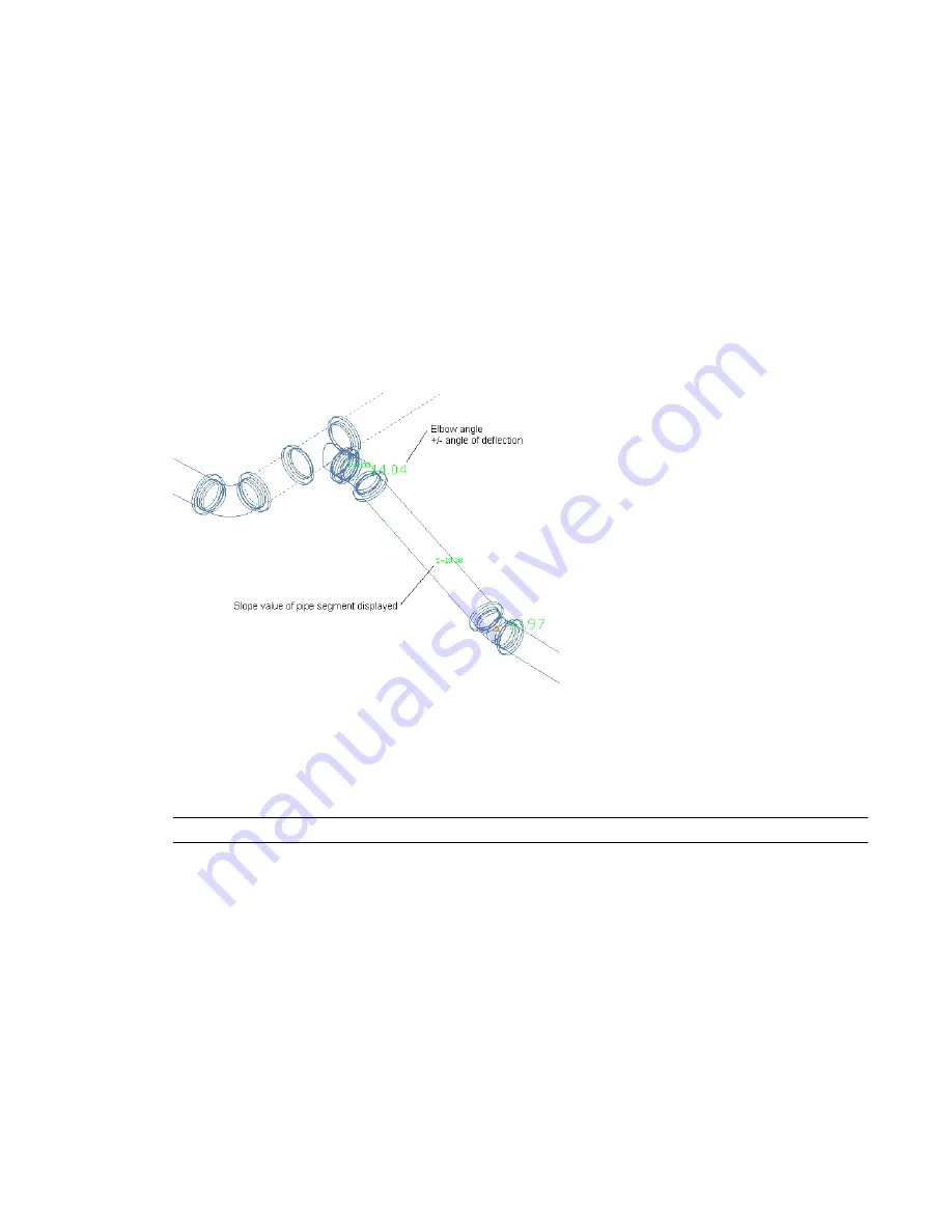
The software displays the current slope value of a pipe segment that is connected to another segment in a
pipe run (
on page 255). The slope value only appears when the software displays possible
on page 254. See the following example.
Slope value displayed
A pipe segment can have a slope value specified on the
on page 286, or it can have a
different slope depending on a particular routing solution that is used. This feature provides an immediate
visual indicator to let you know exactly what solution is used and the associated slope value. To turn off
this feature, enter
PipeSlopeDisplay
on the command line. Then enter
n
at the prompt:
Slope value displayed
during pipe layout [Yes/No] <current value>:
RELATED
For more information on using the sloped piping feature, see
on page 308.
Pipe System Definitions
Pipe system definitions specify display information, such as pipe display by size, layer key settings, rise/drop
display style, and other display properties. You typically associate a system definition to a type of pipe
system, such as chilled water or steam. The settings for a system definition control many of the display
properties of a pipe system. You assign a layer key style to a system definition. This designation dictates the
layer, color, and linetype for the system. You can also configure a system definition to display pipes as 1-line
or 2-line by size.
You can assign a system definition to a
. In the software, pipe runs that have different system
definitions cannot connect to each other without changing the system for the connecting pipe run. You
can, however, assign a system group to different system definitions. This allows pipe runs from different
Pipe System Definitions | 257
Summary of Contents for 235B1-05A761-1301 - AutoCAD MEP 2010
Page 1: ...AutoCAD MEP 2010 User s Guide March 2009 ...
Page 22: ...4 ...
Page 86: ...68 ...
Page 146: ...128 ...
Page 180: ...162 ...
Page 242: ...Modifying the elevation of a duct 224 Chapter 6 Drawing HVAC Systems ...
Page 264: ...246 ...
Page 480: ...462 ...
Page 534: ...516 ...
Page 616: ...598 ...
Page 658: ...640 ...
Page 788: ...770 ...
Page 802: ...784 ...
Page 820: ...802 ...
Page 878: ...860 ...


