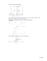


The software adds these entries to the Extended tab of the Properties palette as property set data.
If you do not want to display flanges and add the property set data, clear Enable Flange Connector
Graphics.
To modify values for one or more selected ducts or fittings
6
Select on ore more ducts or fittings, and click Home tab
➤
Build panel
➤
Tools
drop-down
➤
Properties
.
7
On the Design tab of the Properties palette, expand Advanced.
8
For Flange dimensions, enter values for Connector 1 and Connector 2.
Changing the values to zero for a connector causes the flange not to display once you
.
NOTE
You can only display flanges on ducts that have a flange connection type. Their visibility and
display properties are determined by the Connector display component.
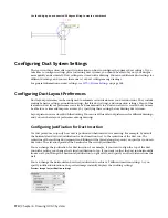
Configuring Flexible Duct Preferences
NOTE
For information on configuring the display properties of flexible duct, see
on page 167.
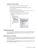
1
, click Manage tab
➤
Preferences panel
➤
Duct
.
NOTE
You can also open Duct Preferences from the Add Ducts dialog. Click
(Preferences) in the
lower left corner of the dialog. Any changes you make to Duct Preferences remain in effect after you
close the Add Ducts dialog.
2
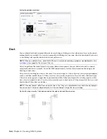
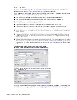
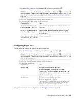
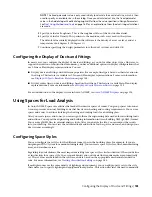
In the Duct Layout Preferences dialog, click the Flex Ducts tab.
3
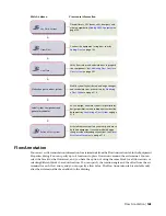
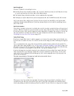
For Segment Mode, specify the default layout method for flex duct:
then…
If you want to…
select
(Line) for Segment Mode. Specify a value for Radius of
Curvature. Any angled transitions in the flex duct segment use this
radius value.
lay out the flex duct as a series of
straight line segments
select
(Arc) for Segment Mode.
lay out the flex duct as a series of arcs
select
(Spline) for Segment Mode.
lay out the flex duct as a complex
curve by specifying points for a spline
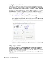
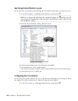
4
Under 1 Line Annotation, for Graphics, select an annotation pattern.
This pattern is applied to flex duct runs after you draw them, and it is visible for flex duct systems
displayed as 1-line.
5
Under 1 Line Annotation, for Pitch, specify a value.
This specifies the interval between the pattern, and it is based on the drawing scale.
6
Repeat the previous steps for 2 Line Annotation.
This pattern is visible for flex duct systems displayed as 2-line.
For information on drawing flex duct runs, see
on page 206.
Configuring Duct Layout Preferences | 179
Summary of Contents for 235B1-05A761-1301 - AutoCAD MEP 2010
Page 1: ...AutoCAD MEP 2010 User s Guide March 2009 ...
Page 22: ...4 ...
Page 86: ...68 ...
Page 146: ...128 ...
Page 180: ...162 ...
Page 242: ...Modifying the elevation of a duct 224 Chapter 6 Drawing HVAC Systems ...
Page 264: ...246 ...
Page 480: ...462 ...
Page 534: ...516 ...
Page 616: ...598 ...
Page 658: ...640 ...
Page 788: ...770 ...
Page 802: ...784 ...
Page 820: ...802 ...
Page 878: ...860 ...


