
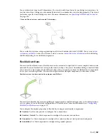


Breaking Duct at Even Intervals
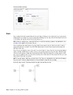
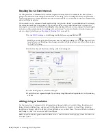
Use this procedure to automatically break duct segments during layout. For example, if a duct system is
going to be fabricated from straight ducts that are 10 feet long, you can configure duct layout preferences
so that straight runs are automatically broken into 10-foot intervals as you draw them. Joints are automatically
added at the break interval.
When turned on, the automatic break length setting is applied to all duct system definitions. For example,
the automatic break length is applied to supply air, return air, or any other defined duct system in the
drawing. If you want to use different break lengths when drawing different systems, change the break length
as shown in this procedure prior to working with each system. You can also break or join duct segments
after you have drawn them; see
on page 234.
1
click Manage tab
➤
Preferences panel
➤
Duct
.
NOTE
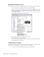
You can also open Duct Preferences from the Add Ducts dialog. Click
(Preferences) in the
lower left corner of the dialog. Any changes you make to Preferences remain in effect after you close
the Add Ducts dialog.
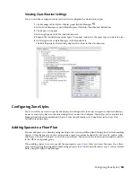
2
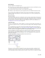
In the Duct Layout Preferences dialog, click the Routing tab.
3
Under During Layout, select Duct Length.
4
Specify the duct segment length by selecting a length from the drop-down list, or by entering
a value.
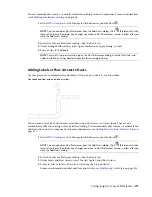
Adding Lining or Insulation
Use this procedure to automatically add insulation or lining to ducts as you draw them. Insulation and
lining display as hidden lines, and are only visible when the duct is viewed as 2-line. When turned on,
insulation or lining is added to all duct system definitions as you draw them. You can add both insulation
and lining to a duct, or you can just add one of them.
NOTE
Insulation and lining are annotation elements only, and are used to visually convey where they are used
on a duct system.
176 | Chapter 6 Drawing HVAC Systems
Summary of Contents for 235B1-05A761-1301 - AutoCAD MEP 2010
Page 1: ...AutoCAD MEP 2010 User s Guide March 2009 ...
Page 22: ...4 ...
Page 86: ...68 ...
Page 146: ...128 ...
Page 180: ...162 ...
Page 242: ...Modifying the elevation of a duct 224 Chapter 6 Drawing HVAC Systems ...
Page 264: ...246 ...
Page 480: ...462 ...
Page 534: ...516 ...
Page 616: ...598 ...
Page 658: ...640 ...
Page 788: ...770 ...
Page 802: ...784 ...
Page 820: ...802 ...
Page 878: ...860 ...


