


General Display Properties
■
Display components: Allows you to adjust settings for the object's individual display components, such
as contours and centerlines
NOTE
Only the active component display properties for the selected object are listed.
■
Display controlled by: Choose from the list of 3 options:
■
Object: Applies changes to all objects with the specified system (for example, Duct System Definition:
Supply - Low Pressure) for which no object overrides are in effect (called system override). This selection
takes precedence over the drawing default setting and style setting.
■
Style: Applies changes to all objects with the specified style (for example, Duct Style: 300 mm Diameter
Round Duct) for which no object overrides are in effect (called style override). This selection takes
precedence over the drawing default setting.
■
System definition: Adds a system definition override to the selected object
■
Domain drawing default: Applies changes to all objects within a domain.
RELATED
See
on page 141.
■
Display representation: Displays the current display representation (such as Plan)
Component Display Properties
■
Basic defines the color, layer, linetype, linetype scale, and lineweight properties of the selected object.
Click
(along the General title bar) for the Apply Display Component Properties to Other Display
Representations worksheet to change other display representations at the same level indicated by the Display
controlled by value.
TIP
A display component must be selected for this button to appear. The corresponding worksheet will only
reflect display representations that can be applied to the selected component.
Changes made on the Display tab become immediately visible in the display representation of the current
drawing. You can also apply changes to other display representations. For example, you can specify whether
a change you make to a display property will apply to the selected component for all objects of that type,
all objects of that style, or only the selected object.
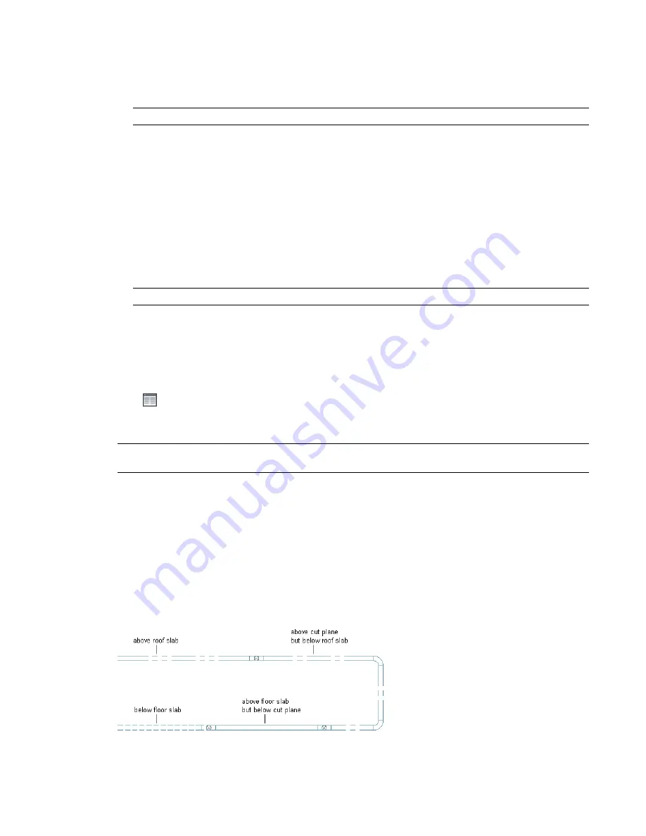
Display of Objects Based on Elevation
In some regions, construction documents must show building system objects differently based on their
elevation. For example, you might be required to display an object below the floor slab in the plan view
with one linetype, and another object above the floor slab but below the cut plane with another linetype.
144 | Chapter 5 Working with Projects
Summary of Contents for 235B1-05A761-1301 - AutoCAD MEP 2010
Page 1: ...AutoCAD MEP 2010 User s Guide March 2009 ...
Page 22: ...4 ...
Page 86: ...68 ...
Page 146: ...128 ...
Page 180: ...162 ...
Page 242: ...Modifying the elevation of a duct 224 Chapter 6 Drawing HVAC Systems ...
Page 264: ...246 ...
Page 480: ...462 ...
Page 534: ...516 ...
Page 616: ...598 ...
Page 658: ...640 ...
Page 788: ...770 ...
Page 802: ...784 ...
Page 820: ...802 ...
Page 878: ...860 ...


