


■
Reference anchors.
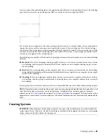
Attach objects by reference to other objects, such as attaching an end-of-line schematic
symbol to a schematic line. When the symbol is moved, the line maintains connectivity and is stretched
to the new location.
Certain objects are, by default, anchored to other objects; however, their behavior can differ slightly depending
on object type. For example, when a schematic symbol is added to an existing line, the symbol is, by default,
attached to the schematic line using a system anchor. The symbol can be easily moved along the line or
moved to another unconnected line of the same system. It cannot, however, be moved outside a line and
stand alone. To do that, you must first remove the anchor between the symbol and line.
Attaching Objects with a Curve Anchor
Use this procedure to attach objects with a curve anchor. With curve anchors, you can attach building
systems objects to the base curve of other building systems objects. The movement of an object anchored
with a curve anchor is constrained by the object to which it is anchored. You can change the position of an
anchored object relative to the curve in the X, Y, and Z directions. You can also rotate and flip the object
along its axes. Curve anchors are best suited for attaching objects to linear objects like segments.
To attach an object with a curve anchor
1
Click Home tab
➤
Build panel
➤
Tools drop-down
➤
Content Browser
.
2
Select the MEP Stock Tool Catalog.
3
In the Content Browser, on the left navigation bar, select Common
➤
Common Items.
4
Click the i-drop icon on the Curve Anchor tool, and drag the tool onto your drawing.
5
Enter at (attach object), and then select the object to be anchored.
6
Select a point on the curve to which to anchor the object.
The object is anchored to the curve at the X position. When the object is placed, the Y and Z
positions are 0.
7
To change the position of the anchored object, do any of the following:
then enter…
If you want to…
s (set curve), select the anchored object, press ENTER,
and then select a new curve.
move the object to a different curve
p (x position), select the anchored object, and select
a point on the base curve. Then enter a distance and
change the position of the object along the curve
by specifying a distance from the center or end of
the curve
specify what to measure to: Near edge, Far edge, or
Center.
r (rotation), select the anchored object, press ENTER,
and then specify a rotation angle.
change the rotation of the anchored object
x (rotation X), select the anchored object, press ENTER,
and then enter or specify a rotation angle.
rotate the object around the X axis
y (rotation Y), select the anchored object, press ENTER,
and then enter or specify a rotation angle.
rotate the object around the Y axis
an (set anchored), select the anchored object, and then
select a point on or near the base curve end.
change the anchored end of the object
8
Press
ENTER
.
Working with Anchors | 109
Summary of Contents for 235B1-05A761-1301 - AutoCAD MEP 2010
Page 1: ...AutoCAD MEP 2010 User s Guide March 2009 ...
Page 22: ...4 ...
Page 86: ...68 ...
Page 146: ...128 ...
Page 180: ...162 ...
Page 242: ...Modifying the elevation of a duct 224 Chapter 6 Drawing HVAC Systems ...
Page 264: ...246 ...
Page 480: ...462 ...
Page 534: ...516 ...
Page 616: ...598 ...
Page 658: ...640 ...
Page 788: ...770 ...
Page 802: ...784 ...
Page 820: ...802 ...
Page 878: ...860 ...


