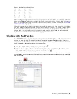

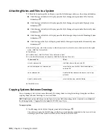


Specifying the Design Rules of a System
The design rules of a system definition are properties that determine the behavior and display of the system.
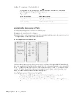
Description
Property
Identifies the system to which the parts are assigned. This is a short system name, typically two
or three characters in length. The abbreviation can be used when labeling objects and creating
schedules.
Abbreviation
Identifies the group of related systems with which the system is associated. System groups allow
you to connect different systems while maintaining their individual system properties. For more
information, see
on page 94.
System Group
Identifies the type of system. Available in electrical and plumbing systems only.
Power & Lighting and Cable Tray are 2 examples of system types in electrical systems. Every
electrical system must have a specified system type.
System Type
Hot Water and Waste are 2 examples of system types in plumbing systems. A plumbing system
does not require a system type. However, sanitary pipe systems that use gray water or black
water must specify the System Type as Waste. Otherwise, the Size Sanitary Pipe command does
not recognize the system as a sanitary pipe system, and you are not be able to size the pipe run.
Identifies the layer to which objects in the system are added.
Layer Key
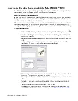
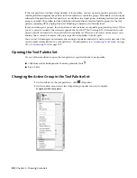
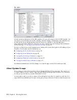
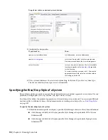
To specify the design rules of a system
1
Within the domain-specific workspace, open the Style Manager, and access the appropriate
system definitions:
■
Click Manage tab
➤
Style & Display panel
➤
Style Manager drop-down
➤
HVAC System
Definitions
.
■
Click Manage tab
➤
Style & Display panel
➤
Style Manager drop-down
➤
Piping System
Definitions
.
■
Click Manage tab
➤
Style & Display panel
➤
Style Manager drop-down
➤
Electrical System
Definitions
.
■
Click Manage tab
➤
Style & Display panel
➤
Style Manager drop-down
➤
Plumbing System
Definitions
.
■
Click Manage tab
➤
Style & Display panel
➤
Style Manager drop-down
➤
Schematic System
Definitions
.
2
In the left pane, select the system, and, in the right pane, click the Design Rules tab.
Specifying the Design Rules of a System | 97
Summary of Contents for 235B1-05A761-1301 - AutoCAD MEP 2010
Page 1: ...AutoCAD MEP 2010 User s Guide March 2009 ...
Page 22: ...4 ...
Page 86: ...68 ...
Page 146: ...128 ...
Page 180: ...162 ...
Page 242: ...Modifying the elevation of a duct 224 Chapter 6 Drawing HVAC Systems ...
Page 264: ...246 ...
Page 480: ...462 ...
Page 534: ...516 ...
Page 616: ...598 ...
Page 658: ...640 ...
Page 788: ...770 ...
Page 802: ...784 ...
Page 820: ...802 ...
Page 878: ...860 ...


