


Geometric Construction Basics 1-3
Using the
LINE command
1. Move the graphics cursor to the first
icon in the Draw toolbar. This icon is
the LINE icon. A Help-tip box appears
next to the cursor and a brief
description of the icon is displayed at
the bottom of the AutoCAD Drawing
Screen: "Creates Straight line
segments: LINE."
2. Select the icon by clicking once with
the left-mouse-button; this will
activate the LINE command. In the
command prompt area, near the bottom
of the AutoCAD Drawing Screen, the
message "_line Specify first point:" is
displayed. AutoCAD expects us to
identify the starting location of a
straight line.
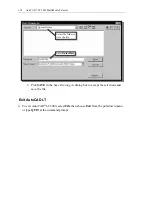
3. Move the graphics cursor inside the Graphics window and watch the display of
the coordinates of the graphics cursor at the bottom of the AutoCAD LT Drawing
Screen. The three numbers represent the location of the cursor in the X and Y
directions. We can treat the Graphics window as if it is a piece of paper and we
are using the graphics cursor as if it is a pencil with which to draw.
4. We will create a freehand sketch of a five-
point star using the LINE command. Create
the sketch near the center of the Drawing
window. Do not be overly concerned with
the size or the accuracy of your freehand
sketch. This exercise is to give you a feel for
the AutoCAD
®
LT 2000 user interface.
5. Start at a location about one-third from the
bottom of the Graphics window, then left-
click once to position the starting point of
our first line. This will be point 1 of our
sketch. Next move the cursor upward and
toward the right side of point 1. Notice the
rubber-band line that follows the graphics
cursor in the Graphics window. Left-click
again and we have created our first line of
the sketch.
5
3
2
1
4
Draw
Toolbar
Coordinates of the location of
the graphics cursor.