background image


10 

Power Sources 

The  MaxiVCI  Mini  operates  on  12-volt  vehicle  power,  which  is  received 

through the vehicle’s DLC. The unit powers on whenever it is connected to 
the vehicle’s DLC. 


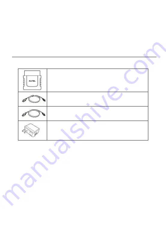
Other Accessories 


MaxiVCI Mini


Connects to the vehicle’s DLC and provides wireless 
connection between the tablet and the vehicle. 


USB Cable (for test)


2 m 


USB Cable (for charging)  

90 cm 


USB External Power Adapter


Together with the mini USB cable, connects the tablet 
to the external DC power port for power supply. 

Summary of Contents for MaxiPRO MP808BT

Page 1: ...information available at the time of printing Autel reserves the right to make changes at any time without notice While information of this manual has been carefully checked for accuracy no guarantee is given for the completeness and correctness of the contents including but not limited to the product specifications functions and illustrations Autel will not be liable for any direct special incide...

Page 2: ... safety of others in the work area the device being used or the vehicle being tested Before using the device always refer to and follow the safety messages and applicable test procedures provided by the manufacturer of the vehicle or equipment being tested Use the device only as described in this manual Read understand and follow all safety messages and instructions in this manual Safety Messages ...

Page 3: ... ignition coil distributor cap ignition wires and spark plugs These components create hazardous voltages when the engine is running Keep a fire extinguisher suitable for gasoline chemical and electrical fires nearby Do not connect or disconnect any test equipment while the ignition is on or the engine is running Keep the test equipment dry clean free from oil water or grease Use a mild detergent o...

Page 4: ...owering Down 15 4 Diagnostics 16 Establishing Vehicle Communication 16 Getting Started 18 Vehicle Identification 20 Navigation 25 Diagnostics Screen Layout 25 Diagnosis 28 Generic OBD II Operations 40 Exiting Diagnostics 44 5 Service 46 Oil Reset Service 46 Electronic Parking Brake EPB Service 50 Battery Management System BMS Service 53 Steering Angle Sensor SAS Service 56 Diesel Particle Filter D...

Page 5: ... Programmer Update 89 10 Shop Manager 90 Vehicle History 91 Workshop Information 93 Customer Manager 94 11 Academy 97 12 Remote Desk 98 13 MaxiFix 100 Navigation 100 Operations 103 14 Support 110 Product Registration 110 Support Screen Layout 111 My Account 111 User Complaint 112 Data Logging 114 Communities 115 Training Channels 117 FAQ Database 118 15 Quick Link 119 16 Function Viewer 120 ...

Page 6: ...aintenance and Service 123 Maintenance Instructions 123 Troubleshooting Checklist 124 About Battery Usage 124 Service Procedures 126 18 Compliance Information 129 19 Warranty 132 Limited One Year Warranty 132 ...

Page 7: ...ility of other modules and optional tools or accessories Conventions The following conventions are used Bold Text Bold text is used to highlight selectable items such as buttons and menu options Example Tap OK Notes and Important Messages Notes A NOTE provides helpful information such as additional explanations tips and comments Example NOTE New Batteries reach full capacity after approximately 3 ...

Page 8: ...nks or links that take you to other related articles procedures and illustrations are available in electronic documents Blue italic text indicates a selectable hyperlink and blue underlined text indicates a website link or an email address link Illustrations Illustrations used in this manual are samples the actual testing screen may vary for each vehicle being tested Observe the menu titles and on...

Page 9: ...ostic and service tool MP808BT provides you with superior special functions including Oil Reset EPB Electronic Parking Brake SAS Steering Angle Sensor BMS Battery Management System and DPF Diesel Particulate Filter There are two main components of the MP808BT system MP808BT Display Tablet the central processor and monitor for the system MaxiVCI Mini Vehicle Communication Interface the device for a...

Page 10: ...municating linking with the vehicle s system The power LED displays green yellow or green depending on power level and operating state A Green Illuminates green when the Display Tablet is charging and the battery level is above 90 Illuminates green when the Display Tablet is powered on and the battery level is above 15 B Yellow Illuminates yellow when the Display Tablet is charging and the battery...

Page 11: ...lder 8 Built in Battery Figure 2 3 Display Tablet Top View 9 Mini USB OTG Port 10 Micro SD Card Slot holds the micro SD card 11 HDMI High Definition Multimedia Interface Port 12 USB Port 13 Lock Power Button turns the device on off with long press or locks the screen with short press Power Sources The tablet can receive power from any of the following sources ...

Page 12: ... USB charging cable and the USB external power adapter The external power supply also charges the internal battery pack Technical Specifications Table 2 1 Specifications Item Description Recommended Use Indoor Operating System AndroidTM 4 4 2 KitKat Processor Cortex A9 processor 1 5 GHz Memory 64GB Display 7 inch LCD capacitive touchscreen with 1024 x 600 resolution Connectivity Mini USB 2 0 USB 2...

Page 13: ...efault brightness Wi Fi on 3 7 V Operating Temp 0 to 55 C 32 to 131 F Storage Temp 20 to 60 C 4 to 140 F Operating Humidity 5 95 non condensing Dimensions W x H x D 237 8 mm 9 4 x 148 6 mm 5 9 x 35 5 mm 1 4 Net Weight 788 g 2 42 lb Protocols ISO9141 2 ISO14230 2 ISO15765 K L Line Flashing Code SAE J1850 VPW SAE J1850PWM ISO11898 Highspeed Middlespeed Lowspeed and Singlewire CAN fault tolerant CAN ...

Page 14: ...to the vehicle s 16 pin DLC directly 2 Power LED refer to Table 2 2 Power LED on the Front Panel on page 8 for details 3 Connection LED refer to Table 2 3 Connection LED on the Front Panel on page 9 for details 4 USB Port provides the easiest connection between the device and the tablet via a USB cable Table 2 2 Power LED on the Front Panel LED Color Description Power Green Lights solid green when...

Page 15: ...solid blue when the device is successfully connected via BT but is not communicating with the vehicle Blinks blue when the device is successfully connected via BT and is communicating with the vehicle Technical Specifications Table 2 4 Specifications Item Description Communications BT V 2 1 EDR USB 2 0 Wireless Frequency 2 4 GHz Input Voltage Range 12 VDC to 24 VDC Supply Current 150 mA 12 VDC Ope...

Page 16: ...t is connected to the vehicle s DLC Other Accessories MaxiVCI Mini Connects to the vehicle s DLC and provides wireless connection between the tablet and the vehicle USB Cable for test 2 m USB Cable for charging 90 cm USB External Power Adapter Together with the mini USB cable connects the tablet to the external DC power port for power supply ...

Page 17: ...m the actual ones Powering Up Long press the Lock Power button on the top right side of the tablet to power on the unit The power LED light will illuminate green The system boots up and displays the lock screen Slide the Lock icon to the left to enter the MaxiPRO Job Menu or slide to the right to unlock Figure 3 1 Sample MaxiPRO MP808BT Job Menu 1 Application Buttons 2 Locator and Navigation Butto...

Page 18: ...Applications Button Name Description Diagnostics Accesses diagnostic functions menu See Diagnostics on page 16 Service Accesses special functions menu See Service on page 46 Shop Manager Allows you to edit and save workshop information and customer data as well as reviewing test vehicle history records See Shop Manager on page 90 Data Manager Accesses the organization system for saved data files S...

Page 19: ...agnostics database See MaxiFix on page 100 Quick Link Provides associated website bookmarks to allow quick access to product update service support and other information See Quick Link on page 119 Function Viewer Provides quick search for the supported functions and vehicles of Autel diagnostic tools See Function Viewer on page 120 Locator and Navigation Buttons Operations of the Navigation button...

Page 20: ... the bottom right corner indicates the tablet is communicating with the MaxiVCI Mini An X will display if the tablet is not connected to VCI Diagnostics Shortcut Returns to the Diagnostics screen Service Shortcut Returns to the Service screen System Status Icons As the tablet is working with the Android operating system you may refer to Android documents for more information By up sliding the bott...

Page 21: ...le communications must be terminated before shutting down the tablet A warning message displays if you attempt to shut down the tablet while it is communicating with the vehicle Forcing a shut down while communicating may lead to ECM problems on some vehicles Please exit the Diagnostics application before powering down To power down the tablet 1 Long press the Lock Power Button 2 Tap Power off opt...

Page 22: ...xiVCI Mini to the vehicle s DLC for both communication and power supply 2 Connect the MaxiVCI Mini to the tablet via BT pairing 3 A green check will display atop the VCI navigation button at the bottom bar on the screen If communication has been established the MP808BT is ready to start vehicle diagnosis Vehicle Connection The tablet communicates with the vehicle via the BT connection provided by ...

Page 23: ...t test vehicles via wireless BT Without the need to repeat the plugging and unplugging procedure which is unavoidable through traditional wired connection BT connection saves you more time and provides higher efficiency Refer to BT Pairing on page 88 for details USB Cable Connection Use the provided USB cable to connect the tablet to the MaxiVCI Mini A green check will display atop the VCI navigat...

Page 24: ...VCI Mini Check if the Power LED on the MaxiVCI Mini is flashing red and if so it indicates there is a hardware problem with the MaxiVCI Mini in this case contact technical support for help B If the MaxiVCI Mini is unable to establish a communication link a prompt message displays with check instructions The following conditions are the possible causes The MaxiVCI Mini is unable to establish a comm...

Page 25: ...Buttons Top Toolbar Buttons The operations of the toolbar buttons at the top of the screen are listed and described in the table below Table 4 1 Top Toolbar Buttons Button Name Description Home Returns to the MaxiPRO Job Menu VIN Scan Provides a fast way to identify the test vehicle See Vehicle Identification on page 20 for details All Displays all the vehicle manufacturers History Displays the st...

Page 26: ...tic system supports four methods for Vehicle Identification 1 Auto VIN Scan 2 Manual VIN Input 3 Automatic Selection 4 Manual Selection Auto VIN Scan The MaxiPRO diagnostic system features the latest VIN based Auto VIN Scan function to identify vehicles and scan all the diagnosable ECUs and run diagnostics on the selected system This function is compatible with 2006 and newer vehicles To perform A...

Page 27: ... will display the vehicle VIN Tap OK at the bottom right to confirm the vehicle VIN If the VIN does not match with the test vehicle s VIN enter VIN manually or tap Read to acquire VIN again 4 Tap OK to confirm the vehicle profile or NO if the information is not correct Figure 4 3 Sample Auto Detect Screen ...

Page 28: ...e tool establishes communication with the vehicle and reads the control unit information Choose Auto Scan to scan all the test vehicles available systems or tap Control Unit to access a specific system to diagnose Figure 4 5 Sample Diagnostic Screen ...

Page 29: ...s application button from the MaxiPRO Job Menu The Vehicle Menu displays 2 Tap the VIN Scan button on the top toolbar to open the dropdown list 3 Select Manual Input Figure 4 6 Sample Diagnostic Screen 4 Tap the input box and enter the correct VIN 5 Tap Done Once the vehicle is identified the Vehicle Diagnostics screen displays 6 Tap Cancel to exit Manual Input ...

Page 30: ...cquired automatically Follow the on screen instruction to display the diagnostic screen Manual Selection When the vehicle s VIN is not automatically retrievable through the vehicle s ECU or the specific VIN is unknown the vehicle can be manually selected This mode of vehicle selection is menu driven repeat the first two steps from the automatic selection operation and tap Manual Selection Through ...

Page 31: ...cs Screen Layout The diagnostic screens typically include four sections 1 Diagnostics Toolbar 2 Status Information Bar 3 Main Section 4 Functional Buttons Diagnostics Toolbar The Diagnostics Toolbar contains a number of buttons such as print and save The table below provides a brief description of the operations of the Diagnostics Toolbar buttons ...

Page 32: ...p the Diagnostics application button from the MaxiPRO Job Menu The Print button on the diagnostic toolbar is available throughout the Diagnostics operations 2 Tap Print A drop down menu displays Tap Print This Page to print a screen shot copy of the current screen 3 A temporary file will be created and sent to the connected computer for printing 4 When the file is transferred successfully a confir...

Page 33: ...s The displayed Functional Buttons vary depending on the stage of operations Functional Buttons can be used to navigate menus to save or clear diagnostic data to exit scanning and to perform a number of other control functions The use of these buttons will be discussed in detail in the following sections of the corresponding test operations Screen Messages Screen messages appear when additional in...

Page 34: ...s to the desired test Tap the screen to make menu selections Diagnosis The Diagnostics application enables a data link to the electronic control system of the test vehicle for vehicle diagnosis The application performs functional tests retrieves vehicle diagnostic information such as trouble and event codes and live data from various vehicle control systems such as engine transmission ABS There ar...

Page 35: ...splays the scanned data in list format Progress Bar indicates the test progress Main Section Column 1 displays the sequence numbers Column 2 displays the scanned systems Column 3 displays the diagnostic indicators describing test results These indicators are defined as follows Indicates that the scanned system may not support the code reading function or there is a communication error between the ...

Page 36: ...f description of the Auto Scan s Functional Buttons operations are displayed in the table below Table 4 3 Functional Buttons Name Description Report Displays the diagnostic data in the report form Quick Erase Deletes codes A warning message screen will display to inform you of possible data loss when this function is selected OK Confirms the test result Continues to the system diagnosis after requ...

Page 37: ... information screen opens upon selection Read Codes displays detailed information of DTC records retrieved from the test vehicle s ECU Erase Codes erases DTC records and other data from the test vehicle s ECU Live Data retrieves and displays live data and parameters from the test vehicle s ECU NOTE Toolbar functions such as saving and printing of test results can be performed throughout diagnostic...

Page 38: ...formation Screen 1 Diagnostics Toolbar Buttons see Table 4 2 Diagnostics Toolbar Buttons on page 26 for detailed descriptions of the operations for each button 2 Main Section the left column displays the item names the right column shows the specifications or descriptions 3 Functional Button ESC a Back button is available tap it to exit after viewing Read Codes This function retrieves and displays...

Page 39: ... displays when freeze frame data is available for viewing selecting this icon will display a data screen which looks behaves similar to the Read Codes screen 3 Functional Button Help tap to view fault code information including fault description condition for fault identification and driver information Freeze Frame tap to view the freeze frame Search tap to search for related fault code informatio...

Page 40: ...ction is selected the screen displays the data list for the selected module The items available for any control module vary by vehicle The parameters display in the order that they are transmitted by the ECM so expect variation between vehicles Gesture scrolling allows for quick movement through data list Using one or two fingers simply swipe the screen up or down to locate the data you want The f...

Page 41: ...he parameters To change the unit mode tap the Setting button on the top toolbar and select a required mode See Unit on page 77 for more information Display Mode There are four types of display modes available for data viewing Select the proper mode for the diagnostic purpose Tap the drop down button on the right side of the parameter name to open a sub menu There are four buttons to configure the ...

Page 42: ...his button to open an edit window on which you can set the waveform color and the line thickness displayed for the selected parameter item Scale Button changes the scale values which are displayed below the waveform graph There are four scales available x1 x2 x4 and x8 Zoom out Button exits full screen display 4 Digital Gauge Mode displays the parameters in form of a digital gauge graph Full Scree...

Page 43: ...reeze Frame displays the retrieved data in freeze frame mode Previous Frame displays previous frame of the freeze data Next Frame advances to the next frame in the freeze data Clear Data clears all previously retrieved parameter values at a cutting point To Top moves a selected data item to the top of the list Graph Merge tap this button to merge selected data graphs for Waveform Graph Mode only T...

Page 44: ...limit value c Buzzer Alarm switches the alarm on and off The alarm function makes a beep sound as a reminder whenever the data reading reaches the preset minimum or maximum point To set threshold limits for the parameter values 1 Tap the Setting functional button at the bottom of the Live Data screen 2 Tap the Selected navigation button 3 Select a parameter item on the left column or enter the ite...

Page 45: ...recording when any DTC is detected 3 DTC Check Mode auto triggers data recording when certain pre selected DTC types are detected 4 Parameter auto triggers data recording when any parameter value reaches the preset threshold b Duration sets the recording time for Auto trigger mode only c Trigger Point reserves a relative percentage of a record length before the data recording start point for refer...

Page 46: ...ics database The diagnostics toolbar buttons at the top of the screen function the same as those available for specific vehicle diagnostics See Table 4 2 Diagnostics Toolbar Buttons on page 26 for details General Procedure To access the OBD II EOBD diagnostics functions 1 Tap the Diagnostics application button from the MaxiPRO Job Menu The Vehicle Menu displays 2 Tap the EOBD button There are two ...

Page 47: ... OBD II Diagnostic Menu NOTE Tapping the button displayed beside the function name opens a bubble with additional function information 4 Select a function option to continue DTC FFD I M Readiness Live Data On Board Monitor Component Test Vehicle Information Vehicle Status NOTE Not all functions are supported by all vehicle ...

Page 48: ...e vehicle OBD II EOBD Codes have a priority according to their emission severity with higher priority codes overwriting lower priority codes The priority of the code determines the illumination of the MIL and the codes erase procedure Manufacturers rank codes differently so expect to see differences between makes Pending Codes These are codes that were generated during the last drive cycle but bef...

Page 49: ... the time the DTC is set Clear DTC This option is used to clear all emission related diagnostic data such as DTCs freeze frame data and manufacturer specific enhanced data from the vehicle s ECM A confirmation screen displays when the clear codes option is selected to prevent accidental loss of data Select Yes to continue or No to exit I M Readiness This function is used to check the readiness of ...

Page 50: ...CVN and other information of the test vehicle Vehicle Status This option is used to check the current condition of the vehicle including communication protocols of OBD II modules retrieved codes amount status of the Malfunction Indicator Light MIL and other additional information Exiting Diagnostics The Diagnostics application remains open as long as there is an active communication with the vehic...

Page 51: ...n tap the Home button on the top toolbar or tap the Back button on the navigation bar at the bottom of the screen 4 Or tap the Home button on the diagnostics toolbar to exit the application directly and go back to the MaxiPRO Job Menu Now the Diagnostics application is no longer communicating with the vehicle and it is safe to open other MaxiPRO applications or exit the MaxiPRO Diagnostic System a...

Page 52: ...B Service BMS Service SAS Service DPF Service After entering each special function the screen will display two application choices Diagnosis and Hot Functions Diagnosis enables the reading and clearing of codes which are sometimes necessary after completing certain special functions Hot Functions consists of sub functions of the selected special function Oil Reset Service Perform reset for the Eng...

Page 53: ...software screens shown in this manual are examples actual test screens may vary for each vehicle being tested Observe the menu headings and on screen instructions to make correct selections To perform oil reset functions 1 Tap the Service application button from the MaxiPRO Job Menu 2 Tap Oil Reset button The vehicle manufacturer screen displays Tap VIN Scan or the vehicle make to acquire vehicle ...

Page 54: ...tap Yes to confirm If not tap No and go to the Settings menu to set the correct date and time Figure 5 2 Sample Oil Reset Service Screen 1 6 The available items will display in a table of four columns CBS value availability service counter and forecast 7 Tap on the value you want to reset and then tap the Correction button on the right bottom of the screen Figure 5 3 Sample Oil Reset Service Scree...

Page 55: ...the corresponding number button to perform the desired function Tap ESC to exit Figure 5 4 Sample Oil Reset Service Screen 3 9 When the reset is done the screen will display Service function finished Tap Continue to exit Figure 5 5 Sample Oil Reset Service Screen 4 ...

Page 56: ...o be deactivated before carrying out any maintenance diagnostic work on the brake system This can be done from the tool menu Only perform maintenance work when the vehicle is stationary and on level ground Ensure that the EPB control system is reactivated after the maintenance work has been completed NOTE Autel accepts no responsibility for any accident or injury arising from the maintenance of th...

Page 57: ... Press ESC button to exit Parking brake Initial operation This service function would start up the parking brake It must be conducted after the following operation Terminal 15 OFF Terminal 15 ON Press brake pedal forcefully Keep brake pedal pressed Apply parking brake pull button Release parking brake button press Figure 5 7 Sample Parking brake Initial operation ...

Page 58: ...rvice function or the No button at the bottom left to exit 2 When the operation is successfully completed a Completed successfully message will display on the screen press Continue to exit Figure 5 8 Sample Parking brake Initial operation Screen 2 ...

Page 59: ...market battery has the same specifications such as capacity and type as the existing battery If the original battery is replaced with a different type of battery e g a lead acid battery is replaced with an AGM battery or a battery with a different capacity mAh the vehicle may require reprogramming of the new battery type in addition to performing the battery reset Consult the vehicle manual for ad...

Page 60: ...p Register battery exchange in the Battery function list The list may vary by test vehicle Figure 5 9 Sample BMS Function List 4 Tap on the desired function to complete In our example tap F1 Register battery replacement Figure 5 10 Sample BMS Screen 1 5 Read carefully the information on the screen and scroll through list to view all functions There are four functions listed F1 Enter battery replac...

Page 61: ...ESC End service function Figure 5 11 Sample BMS Screen 2 Take the second function as an example Figure 5 12 Sample BMS Screen 3 6 Read carefully the information on the screen and tap Continue to the next screen 7 Follow the on screen instructions to input the data matrix code of the newly installed battery which should be on the label of the battery Tap OK to continue ...

Page 62: ...teering wheel position as the straight ahead position in the steering angle sensor EEPROM Therefore the front wheels and the steering wheel must be set exactly to the straight ahead position before calibration In addition the vehicle identification number is also read from the instrument cluster and stored permanently in the steering angle sensor EEPROM On successful completion of calibration the ...

Page 63: ... When interpreting DTCs retrieved from the vehicle always follow the manufacturer s recommendation for repair 2 All software screens shown in this manual are examples actual test screens may vary for each test vehicle Pay attention to the menu titles and on screen instructions to make correct option selections 3 Before starting the procedure make sure the vehicle has ESC button Look for the button...

Page 64: ... by vehicles 1 Tap Steering Angle Sensor adjustment from the SAS function menu to enter the function screen 2 The steering angle must be calibrated after following jobs Replacement of steering column switch cluster Encoding of DSC control unit Adjustment work on steering geometry Working on steering and or front axle Tap continue to the next step Figure 5 16 Sample SAS Function Screen 1 ...

Page 65: ... sensor on completion of the following work Encoding of DSC control unit Replacement of DSC control unit Tap continue to proceed Figure 5 17 Sample SAS Function Screen 2 4 Read the complete information carefully and tap Yes to the next step tap No to exit Figure 5 18 Sample SAS Function Screen 3 ...

Page 66: ...by step on screen instruction to continue Figure 5 19 Sample SAS Function Screen 4 6 Read the complete information carefully and tap Yes to end the test module or tap No to continue Figure 5 20 Sample SAS Function Screen 5 ...

Page 67: ... ahead position The steering wheel must be positioned horizontally Tap Continue to the next step Figure 5 21 Sample SAS Function Screen 6 8 Read the attention carefully and tap Continue to the next step Figure 5 22 Sample SAS Function Screen 7 ...

Page 68: ...step please wait until the Adjustment was successful message displayed Tap Continue to proceed Figure 5 23 Sample SAS Function Screen 8 10 Confirm the degrees of the steering angle and then tap Yes to continue Figure 5 24 Sample SAS Function Screen 9 ...

Page 69: ...63 11 Adjustment of the steering angle was carried out correctly Tap Continue to end the test module Figure 5 25 Sample SAS Function Screen 10 ...

Page 70: ...F light and Check Engine indicators displaying A service regeneration can be requested in the workshop using the diagnostic tool Before performing a forced DPF regeneration using the tool check the following items The fuel light is not on No DPF relevant faults are stored in system The vehicle has the correct spec engine oil The oil for diesel is not contaminated Before diagnosing a problem vehicl...

Page 71: ... You can tap VIN Scan or the vehicle make to acquire vehicle VIN information and tap Yes to confirm See Vehicle Identification on page 20 for detail 3 Tap the desired function in the DPF function list The list may vary by test vehicle Figure 5 26 Sample DPF Service Function Menu 4 Follow the step by step on screen instruction to complete the service Using Diesel particulate filter Request regenera...

Page 72: ...efully and tap Continue to the next step Figure 5 27 Sample DPF Function Screen 1 3 A series of instruction screens display for users to perform the Request regeneration step by step Figure 5 28 Sample DPF Function Screen 2 ...

Page 73: ...utes Tap Continue to the next step Figure 5 29 Sample DPF Function Screen 3 5 The tool will display a function list menu as below Press the corresponding number button to perform the desired function Tap F1 to perform Request regeneration or tap ESC to end this procedure Figure 5 30 Sample DPF Function Screen 4 ...

Page 74: ...ration was successfully requested message will display on the screen Tap Continue to the next step Figure 5 31 Sample DPF Function Screen 5 7 Switch off the ignition and tap Continue to the next step Figure 5 32 Sample DPF Function Screen 6 ...

Page 75: ... engine Read the notes on the screen carefully and then tap Continue to the next step Figure 5 33 Sample DPF Function Screen 7 9 Read the information carefully and then tap Continue to the next step Figure 5 34 Sample DPF Function Screen 8 ...

Page 76: ...to the next step Figure 5 35 Sample DPF Function Screen 9 11 A series of instruction screens display for users to perform the particle filter regeneration step by step Follow the onscreen instructions and tap Continue button until the tool displays the regeneration status as below Figure 5 36 Sample DPF Function Screen 10 ...

Page 77: ...71 12 Tap F1 to continue display the status of current regeneration or tap ESC to exit Figure 5 37 Sample DPF Function Screen 10 ...

Page 78: ...opens the file system menu Different file types are sorted separately under different options there are five types of information files to be viewed or played back Figure 6 1 Sample Data Manager Main Screen Operations Data Manager Operations are based on toolbar controls Details are explained in the following sections Image Files The Image section contains all captured screenshot images ...

Page 79: ...n Back Returns to the previous screen Enter Edit Tap this button to display the editing toolbar Print delete or view image information Cancel Tap this button to close the editing toolbar or cancel file search Search Quickly locates the image file by entering the vehicle name test path file name or file info Info Tap this button to display the details Print Tap this button to print the selected ima...

Page 80: ...Fi printer capabilities can be used To install the printer driver program 1 Please download the Maxi PC Suite from www autel com Support Downloads Autel Update Tools and install to your windows PC The Maxi PC Suite consists of Autel Printer MaxiSys Pinter and PC Suite 2 Double click on Setup exe item 3 Select the installation language and the printer driver installation wizard will load momentaril...

Page 81: ...isplay The standard Adobe Reader application is used for file viewing and editing please refer to the associated Adobe Reader manual for detailed instructions Review Data The Review Data section allows playback of the recorded data frames of live data streams On the Review Data main screen select a record file to playback Figure 6 3 Sample Data Playback Screen 1 Drop down Toolbar tap the button at...

Page 82: ...lable vehicle diagnostic application can be reviewed Tap on the vehicle manufacturer icon that you wish to delete The selected icon will display a blue check at the upper right corner Tap the Delete button on the top bar to delete the firmware from the system database Data Logging The Data Logging section allows you to launch Support platform directly to view all records of all sent or unsent save...

Page 83: ...ures to adjust the device s system settings Unit This option allows you to adjust the measurement unit for the diagnostic system To adjust the unit setting 1 Tap the Settings application on the MaxiPRO Job Menu 2 Tap the Unit option on the left column 3 Select the appropriate measurement unit Metric or English A tick icon will display to the right of the selected unit 4 Tap the Home button on the ...

Page 84: ...etting 1 Tap the Settings application on the MaxiPRO Job Menu 2 Tap the Language option on the left column Figure 7 2 Sample Language Setting Screen 3 Select the appropriate language A check will display to the right of the selected language 4 Tap the Home button on the top left corner to return to the MaxiPRO Job Menu or tap another setting to adjust ...

Page 85: ...d files to the printer through the networked PC via Wi Fi connection 4 Tap the Home button on the top left corner to return to the MaxiPRO Job Menu or tap another setting to adjust Figure 7 3 Sample Printing Setting Screen Printing via APP MP808BT provides the most convenient printing method printing via APP To realize this function please make sure a Wi Fi printer is available and then purchase a...

Page 86: ...er runs automatically after the installation The computer printer and the tablet must be connected to the same network To perform printing through the computer 1 Run the MaxiSys Printer program on the computer 2 Click Test Print to make sure the printer is working successfully 3 Tap the Print button on the toolbar A temporary document will be created and sent to the computer for printing and the r...

Page 87: ...the left column 3 Tap the ON OFF button to enable or disable the Notifications function If the function is enabled the button turns blue or if disabled the button turns gray Figure 7 4 Sample Notification Screen 4 Tap the Home button on the top left corner to return to the MaxiPRO Job Menu or choose another setting to adjust When the Notification Center function is turned on and new messages are r...

Page 88: ...To set auto system or vehicle update 1 Tap the Settings application on the MaxiPRO Job Menu 2 Tap the Auto Update option on the left column The three auto update items display on the right Figure 7 5 Sample Auto Update Screen 3 Select the update type to schedule Toggle the button to ON 4 To set download time use the and button or tap on the numbers and the manual input screen will display Tap Done...

Page 89: ...stem settings including wireless and network settings sound and display screen settings and system security settings To enable the App Switcher function 1 Tap the Settings application on the MaxiPRO Job Menu 2 Tap the System settings option on the left column Figure 7 7 Sample System Settings Screen 3 Tap the App Switcher option on the left column 4 Check the box beside Always show the App Switche...

Page 90: ... About displays information regarding the MaxiPRO diagnostic device including the product name version hardware and serial number To check the MaxiPRO product information in About 1 Tap the Settings application on the MaxiPRO Job Menu 2 Tap the About option on the left column The product information screen displays on the right 3 Tap the Home button on the top left corner to return to the MaxiPRO ...

Page 91: ...tes improve the MaxiPRO applications capabilities typically by adding new tests new model coverage or by adding enhanced applications Software Update The tablet automatically searches for available updates for all of the MaxiPRO software when it is connected to the Internet Any updates that are found can be downloaded and installed on the device This section describes update procedures in the Maxi...

Page 92: ...p the About button to display a function list with additional software update details Middle Column displays a brief introduction about the new changes to the software operation or capabilities Tap i button to open an information screen to view more details and tap the dim area around to close the window Right Column according to the operation status of each software item the button displays diffe...

Page 93: ...ion and the latest version of the VCI software will be displayed after a few seconds Click Update Now to update the VCI software if available Update via PC 1 Down the Maxi PC Suite from www autel com Support Downloads Autel Update Tools and install it onto your windows PC 2 Using a USB cable connect the MaxiVCI Mini to a PC 3 Launch the PC Suite on the PC which is installed after the installation ...

Page 94: ...I software only when the MaxiPRO tablet and the MaxiVCI Mini are connected by a USB cable this function is used to update VCI software via Internet 2 BT Setting The BT Setting screen displays the types and product serial numbers for all the devices available for pairing Tap a required device to start pairing The BT status icon displayed to the left of the device name indicates the received signal ...

Page 95: ... When paring is successfully done the connection status displayed to the right of the device name is shown as Paired 8 Once paired the VCI button on the system Navigation bar at the Connection LED on the MaxiVCI Mini illuminates solid blue This signifies that the tablet is connected to the MaxiVCI Mini and is ready to perform vehicle diagnosis 9 Tap the paired device again to unpair it 10 Tap the ...

Page 96: ...e table below Table 10 1 Top Toolbar Buttons in Shop Manager Button Name Description Back Returns to the previous screen Diagnostics Tap this button to access vehicle Diagnostics menu Enter Edit Displays the editing toolbar to print or delete the selected file Delete Deletes the selected vehicle record Search Enters the vehicle name or test path to retrieve the vehicle record Cancel Cancels edit o...

Page 97: ...zed details Tap on a record to resume a diagnostic session on a stored vehicle Figure 10 1 Sample Vehicle History Screen To activate a test session for the recorded vehicle 1 Tap the Shop Manager application on the MaxiPRO Job Menu 2 Select Vehicle History 3 Tap the Diagnostics button at the bottom of the thumbnail of a vehicle record item 4 Or tap the vehicle record thumbnail to view record 5 A H...

Page 98: ... The form also includes retrieved DTC from previous test and all information manually inputted by the technician Figure 10 2 Sample Historical Test Record Sheet To edit the Historical Test record sheet 1 Tap the Shop Manager application on the MaxiPRO Job Menu 2 Select Vehicle History 3 Select the specific vehicle history record thumbnail from the main section The Historical Test record sheet disp...

Page 99: ...e to save the updated record sheet or tap Cancel to exit without saving Workshop Information The Workshop Information form allows you to edit input and save the detailed workshop information such as shop name address phone number and other remarks which when printing vehicle diagnostic reports and other associated test file will display as the header of the printed documents Figure 10 3 Sample Wor...

Page 100: ...Photo to choose from an existing image 5 Some customers may have more than one vehicle for service you can always add new vehicle information to the account to be correlated Tap Add New Vehicle Information and then fill in the vehicle information Tap the x button to cancel adding 6 Tap Done to save the account or tap Cancel to exit without saving To edit a customer account 1 Tap the Shop Manager a...

Page 101: ... the request History Notes Use the History Notes function to add audio and video records text notes and photos for the associated customer account To access History Notes 1 Tap the Shop Manager application on the MaxiPRO Job Menu 2 Select Customer Manager or Vehicle History 3 Select a customer account by tapping the corresponding name card A Customer Information sheet displays if Customer Manager ...

Page 102: ...cates the required note by entering the note title Cancel Cancels edit or file search Edit Tap this button to open an edit window to edit notes Add Notes Adds new note to History Notes Save Saves notes To add a note in History Notes 1 Access History Notes 2 Tap the Add Notes button An edit window displays 3 Tap on the Title bar to input a note title 4 Tap on the blank space below to edit a text no...

Page 103: ... articles and technical bulletins produced by top notch technicians and product experts Please view the materials that are saved on the tablet or view technical articles from our online forum by clicking the links displayed under this application ...

Page 104: ...nts can be reached separately Computers and mobile devices that run TeamViewer are identified by a globally unique ID The first time the Remote Desk application is started this ID is generated automatically based on the hardware characteristics and will not change later on Make sure the tablet is connected to the Internet before launching the Remote Desk application so that the tablet is accessibl...

Page 105: ...is her computer at the same time in order to provide support and take control of the tablet remotely 4 Provide your ID to the partner and wait for him her to send you a remote control request 5 A popup displays to ask for your confirmation to allow remote control on your device 6 Tap Allow to accept or tap Deny to reject Refer to the associated TeamViewer documents for additional information ...

Page 106: ...ooting resources and the advisory reports from the MaxiPRO users from all over the world Information in the MaxiFix database is organized into a series of diagnostic tips that are designed to quickly lead you to the root cause of a particular problem on the test vehicle Navigation You need to register the device to your online account before launching the MaxiFix platform see Product Registration ...

Page 107: ...tion by entering keywords codes or problems Select Vehicle Button The Select Vehicle button on the Header allows you to specify the vehicle which you want to research on MaxiFix by selecting each of the vehicle attribute from a sequence of option lists This feature helps to filter out the searches that allow only the information that applies to the identified vehicle to display NOTE All attributes...

Page 108: ...ect the make of the vehicle from the list d Select the model of the vehicle from the list e Select the submodel of the vehicle from the list f Select the engine of the vehicle from the list After completing the vehicle selection procedure the identified vehicle is shown on the Header 2 Enter a Search Term MaxiFix has an exclusive one stop lookup that helps you find all of MaxiFix resources by one ...

Page 109: ...epairing vehicle issues You can also post a comment about how the tip has helped you as reference to other members Operations The Navigation Menu is at the bottom of the screen Selecting the items on the Navigation Menu allows you to switch between the main sections on MaxiFix These main sections include Home shows all questions and allows you to specify questions about one or multiple makes Searc...

Page 110: ...ix the second option on the Navigation Menu at the bottom of the screen presents search results for the specified vehicle Search results are listed in various categories All includes all search results including related Questions Tips and Real Fixes to your search Questions presents a list of open Question discussed in the community that may be pertinent to your search Tips presents a list of Tips...

Page 111: ...c work Tap Cancel to cancel your question and return to the Ask page Tap Submit to post your question to the community Tap Attach File to include images or reference files with your question You are requested to select one Adopted Answer from all of the responses and then close the question For details please refer to My Messages on page 107 My MaxiFix My MaxiFix the fourth option on the Navigatio...

Page 112: ... a concise and complete description of the fix for a particular vehicle repair issue To create a new MaxiFix Tip 1 Select My MaxiFix from the Navigation Menu 2 Select Select Vehicle from the Header and enter the identifying attributes of the vehicle you are writing the Tip about 3 On the My MaxiFix page find Share a Tip click this link to open the My Tips page 4 Enter the Tip subject in the Subjec...

Page 113: ...er of the new and unread messages The displayed number will be reduced correspondingly after viewing The message notification will appear under the following two conditions 1 Your question or answer is replied by other MaxiFix community members 2 Your answer is marked as the Adopted by the MaxiFix community member who asked the question Tap My Messages select and open the message you want to read ...

Page 114: ...ewarding System 1 A score of 4 is awarded if your answer is selected as the Adopted Answer 2 A score of 3 is awarded when you close a question 3 A score of 2 is awarded if your closed question is marked as Adopted by no less than 20 community members 4 A score of 1 is awarded if your answer is selected as the Adopted Answer for a closed question which is marked as Adopted by no less than 20 commun...

Page 115: ...109 window To allow the administrator to respond to your question or issue the following information should be provided Your name A contact email address A contact phone number ...

Page 116: ...an Autel account sign in with your account ID and password 3 If you are a new member to Autel click on the Create Autel ID button on the left side of the screen to create an ID 4 Enter the required information in the input fields and click Get Verification Code button to get a verification code for email validation 5 The online system will automatically send a verification code to the registered e...

Page 117: ...loads and updates the screen Figure 14 1 Sample Support Application Screen The main section of the Support screen is divided into two sections The narrow column on the left is the main menu select one subject from the main menu to display the corresponding functional interface on the right My Account The My Account screen displays the comprehensive information of the user and the product which is ...

Page 118: ...re update history including the product serial number software version or name and the update time Service Info The Service Info section displays a detailed record list of the device s service history information The device s serial number and a detailed repair report such as the fault type changed components or system reinstallation will be listed User Complaint The User Complaint screen allows y...

Page 119: ...complaint has been replied by the service personnel and requires feedback from the customer Closed indicates the complaint case has been processed resolved and closed To view the detailed complaint session tap the button on the right side of the case item To establish a new complaint session 1 Register the product online 2 Tap the Support application on the MaxiPRO Job Menu The device information ...

Page 120: ...h the online account 3 Tap Complaint on the Main Menu 4 Select an existing complaint case item on the record list by tapping the button on its right side The screen displays the complaint session details 5 Tap the Post Reply button on the upper right side after viewing to make a reply An edit screen displays 6 Input the content in the input field and if necessary upload an attaching file 7 Tap Sub...

Page 121: ...xts Or tap the Audio button to record a voice message or camera button to include an image 4 Tap Send to send message to the technical center Communities The Communities section launches and synchronizes with the Technical Forums on Autel s official website www autel com where you are allowed to discuss technical topics or share information with as well as ask for technical advices or offer techni...

Page 122: ...This will help other members with similar interest to find your post 5 Tap OK to submit the post To join and reply to a discussion post 1 Select a forum group whether by the product or the features on the Communities Home screen A list of the latest posts is displayed 2 Select a specific category on the Categories menu to better pinpoint the topics you are most interested with 3 Tap the button on ...

Page 123: ... displays the user s personal information and member status The Related links allow you to check the Top Users ranked according to their points and levels in the communities as well as to find out other online users Avatar allows you to select an image to set as your personal Avatar to be displayed in the communities Stuff displays all the discussions you ve posted at various forums in a list Trai...

Page 124: ...asked and answered about the use of Autel s online member account and shopping and payment procedures Account displays questions and answers about the use of Autel s online user account Shopping Payment displays questions and answers about online product purchase and payment methods or procedures ...

Page 125: ...ditional in automotive service sites Figure 15 1 Sample Quick Link Screen To open a quick link 1 Tap the Quick Link application on the MaxiPRO Job Menu The Quick Link application screen displays 2 Select a website thumbnail from the main section The Chrome browser is launched and the selected website is opened ...

Page 126: ...y the vehicle 1 Tap the Function Viewer application on the MaxiPRO Job Menu The Function Viewer application screen displays 2 Tap the tool name on the top left to drop down the tool list tap the one you want to search Figure 16 1 Sample Function Viewer Screen 1 3 Tap the vehicle brand model and year you want to search 4 All the functions support by the selected tool for the selected vehicle displa...

Page 127: ...me on the top left to drop down the tool list tap the one you want to search 3 Type in the function you want to search to the top right search column All the vehicles with this function will be listed with 8 columns the Brand Model Year System Sub system Function Sub function and Version NOTE Fuzzy search is supported type in part of the function you want to search can also find you all the relate...

Page 128: ...122 Figure 16 3 Sample Function Viewer Screen 3 ...

Page 129: ...hands Do not store the devices in humid dusty or dirty areas Check the housing wiring and connectors for dirt and damage before and after each use At the end of each work day wipe the device housing wiring and connectors clean with a damp cloth Do not attempt to disassemble your tablet or the MaxiVCI Mini Do not drop or cause severe impact to the devices Use only authorized battery chargers and ac...

Page 130: ...o a power source or the battery is charged D When you are unable to charge the tablet Your charger maybe out of order Contact your nearest dealer You may be attempting to use the device in an overly hot cold temperature Try changing the charging environment Your device may have not been connected to the charger properly Check the connector NOTE If your problems persist please contact Autel s techn...

Page 131: ... qualified with device per the standard Use of an unqualified battery or charger may present a risk of fire explosion leakage or other hazard Avoid dropping the tablet If the tablet is dropped especially on a hard surface and the user suspects damage contact support Move the tablet closer to your network s base station to improve battery life The battery recharging time varies depending on the rem...

Page 132: ...l support autel com Address 7th 8th 10th floor Building B1 Zhiyuan Xueyuan Road Xili Nanshan Shenzhen 518055 China AUTEL NORTH AMERICA Phone 855 AUTEL US 855 288 3587 Monday Friday 9am 6pm EST Website www autel com Email ussupport autel com Address Suite 200 175 Central Avenue Farmingdale New York USA 11735 AUTEL EUROPE Phone 0049 0 61032000520 Website www autel eu Email sales eu autel com support...

Page 133: ...it in The following information must be included Contact name Return address Telephone number Product name Complete description of the problem Proof of purchase for warranty repairs Preferred method of payment for non warranty repairs NOTE For non warranty repairs payment can be made with Visa Master Card or with approved credit terms Send the device to your local agent or to the below address 8th...

Page 134: ...128 Your purchase order should include the following information Contact information Product or part name Item description Purchase quantity ...

Page 135: ...odifications not expressly approved by the party responsible for compliance could void the user s authority to operate the equipment This equipment has been tested and found to comply with the limits for a Class B digital device pursuant to Part 15 of the FCC Rules These limits are designed to provide reasonable protection against harmful interference in a residential installation This equipment g...

Page 136: ...Specific Absorption Rate or SAR The SAR limit set by the FCC is 1 6 W Kg Tests for SAR are conducted using standard operating positions accepted by the FCC with the device transmitting at its highest certified power level in all tested frequency bands Although the SAR is determined at the highest certified power level the actual SAR level of the device while operating can be well below the maximum...

Page 137: ...CE This product is declared to conform to the essential requirements of the following Directives and carries the CE mark accordingly EMC Directive 2014 30 EU R TTE Directive 2014 53 EU Low Voltage Directive 2014 35 EU ...

Page 138: ...g of the device Some states do not allow limitation on how long an implied warranty lasts so the above limitations may not apply to you This warranty does not apply to 1 Products subjected to abnormal use or conditions accident mishandling neglect unauthorized alteration misuse improper installation or repair or improper storage 2 Products whose mechanical serial number or electronic serial number...

Page 139: ...133 IMPORTANT All contents of the product may be deleted during the process of repair You should create a back up copy of any contents of your product before delivering the product for warranty service ...

Reviews: