background image

85 

Button 

Name 

Description 


Review Data 

View recorded data. 


Uninstall 
Apps 

Uninstall applications. 


Data Logging 

View  communications  with  Autel  support  service 
and ECU information for the test vehicle. The saved 
data  can  be  reported  and  sent  to  the  technical 
center via the Internet. 

7.1 Vehicle History 


This function stores vehicle test records, including vehicle information and the retrieved 
DTCs from previous diagnostics sessions. Test information is summarized and displays 
in  an  easy-to-read  table  listing.  The  Vehicle  History  also  provides  direct  access  to  the 
previously tested vehicles and allows you to directly restart a diagnostics session without 
needing to perform auto or manual vehicle selection. 


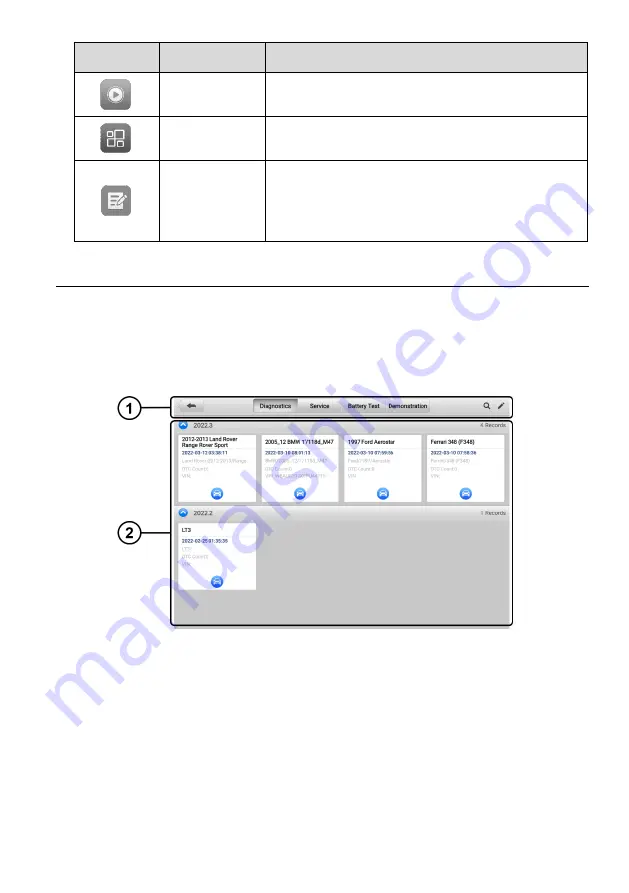
Figure 7-2 

Vehicle History Screen 

1.  Top Toolbar Buttons 

— navigation and application controls. 

2.  Main Section 

— displays all the test records. 


To activate a test session for a recorded vehicle


1.  Tap 

Data Manager 

on the MaxiCOM Job Menu. 

2.  Select 

Vehicle History

 to open the screen. Tap 

Diagnostics

Service 

or

 Battery 

Test

 to select diagnostics test records or service test records.   

3.  Tap the 

Diagnostics 

icon at the bottom of the thumbnail of a vehicle record. 

Summary of Contents for MaxiCOM Ultra Lite

Page 1: ...tion available at the time of printing Autel reserves the right to make changes at any time without notice While information of this manual has been carefully checked for accuracy no guarantee is given for the completeness and correctness of the contents including but not limited to the product specifications functions and illustrations Autel will not be liable for any direct special incidental or...

Page 2: ...s in the work area the device being used or the vehicle being tested Before using the device always refer to and follow the safety messages and applicable test procedures provided by the manufacturer of the vehicle or equipment being tested Use the device only as described in this manual Be sure to read understand and follow all safety messages and instructions in this manual Safety Messages Safet...

Page 3: ...esting Be extra cautious when working around the ignition coil distributor cap ignition wires and spark plugs These components create hazardous voltages when the engine is running Keep a fire extinguisher suitable for gasoline chemical and electrical fires nearby Do not connect or disconnect any test equipment while the ignition is on or the engine is running Keep the test equipment dry clean and ...

Page 4: ...4 4 CONTROL UNIT 35 4 5 ECU INFORMATION 36 4 6 TROUBLE CODES 37 4 7 LIVE DATA 38 4 8 ACTIVE TEST 45 4 9 SPECIAL FUNCTIONS 46 4 10 PROGRAMMING AND CODING 47 4 11 GENERIC OBDII OPERATIONS 50 4 12 DIAGNOSTICS REPORT 53 4 13 EXIT DIAGNOSTICS 59 5 INTELLIGENT DIAGNOSTICS 61 5 1 ACCESSING INTELLIGENT DIAGNOSTICS FUNCTION 61 5 2 INTELLIGENT DIAGNOSTICS OPERATION 69 6 SERVICE 79 6 1 OIL RESET SERVICE 79 6...

Page 5: ...IONS 92 9 UPDATE 96 10 VCI MANAGER 98 10 1 WI FI CONNECTION 98 10 2 VCI BLUETOOTH PAIRING 99 10 3 BAS BLUETOOTH PAIRING 100 10 4 VCI UPDATE 101 10 5 BAS UPDATE 102 11 BATTERY TEST 104 11 1 MAXIBAS BT506 TESTER 104 11 2 TEST PREPARATION 106 11 3 IN VEHICLE TEST 107 11 4 OUT VEHICLE TEST 112 12 SUPPORT 115 12 1 PRODUCT REGISTRATION 115 12 2 SUPPORT SCREEN LAYOUT 115 12 3 MY ACCOUNT 116 12 4 TRAINING...

Page 6: ...S 124 16 2 OPERATIONS 128 17 USER FEEDBACK 130 18 MAINTENANCE AND SERVICE 131 18 1 MAINTENANCE INSTRUCTIONS 131 18 2 TROUBLESHOOTING CHECKLIST 131 18 3 ABOUT BATTERY USAGE 132 18 4 SERVICE PROCEDURES 133 19 COMPLIANCE INFORMATION 135 20 WARRANTY 137 20 1 12 MONTH LIMITED WARRANTY 137 ...

Page 7: ...provides helpful information such as additional explanations tips and comments Important IMPORTANT indicates a situation that if not avoided may result in damage to the tablet or vehicle 1 1 3 Hyperlinks Hyperlinks are available in electronic documents Blue text indicates a selectable hyperlink a website link or an email address link 1 1 4 Illustrations Illustrations used in this manual are sample...

Page 8: ...ured in the viewfinder 3 Tap the camera icon on the right side of the screen The viewfinder now shows the captured picture and auto saves the taken photo 4 Tap the thumbnail image on the top right corner of the screen to view the stored image 5 Tap the Back or Home button to exit the camera application ...

Page 9: ...p by step guidance to ensure the repair is done correctly and efficiently There are two main components to the MaxiCOM system MaxiCOM Tablet the central processor and monitor for the system MaxiFlash VCI Vehicle Communication Interface This manual describes the construction and operation of these devices and how they work together to deliver diagnostics solutions MaxiCOM Tablet 2 1 1 Function Desc...

Page 10: ...ry level is above 15 Yellow Lights yellow when the tablet is charging and the battery level is below 90 Red Lights red when the tablet is powered on and the battery level is below 15 Figure 2 2 MaxiCOM Tablet Back View 6 Docking Station Port 7 Collapsible Stand extends from the back to allow hands free viewing of the tablet 8 Speaker 9 Rear Camera 10 Camera Flash Figure 2 3 MaxiCOM Tablet Top View...

Page 11: ...on 1 DC Power Port connects to the AC DC adapter for power supply 2 Charging Dock holds the tablet for optimum viewing and convenient charging 3 Status Indicator The Indicator displays differently in response to the tablet status described below A Green battery power of the tablet is sufficient 90 B Yellow battery level is above 14 but below 90 C Red battery level is below 14 NOTE Ensure the charg...

Page 12: ...blet can be powered from an electrical outlet using the AC DC power adapter or docking station The AC DC power supply also charges the internal battery pack 2 1 2 3 Vehicle Utility Power Port The tablet can be powered from any utility power port on the test vehicle through a direct cable connection The vehicle power cable connects to the DC power supply port on the top side of the tablet 2 1 3 Tec...

Page 13: ...ry Charging via 12 V AC DC power supply with the temperature between 0 C and 45 C Input Voltage 12 V 3 A Adapter Operating Temp 0 to 50 C 32 to 122 F Storage Temp 20 to 60 C 4 to 140 F Dimensions WxHxD 366 5 mm 14 43 x 280 9 mm 11 06 x 34 mm 1 34 Weight 2 18 kg 4 81 lb Protocols DoIP PLC J2497 ISO 15765 SAE J1939 ISO 14229 UDS SAE J2411 Single Wire Can GMLAN ISO 11898 2 ISO 11898 3 SAE J2819 TP20 ...

Page 14: ...with the vehicle system 5 Connection LED Lights solid green when the device is properly connected with the tablet via the USB cable Lights solid cyan blue green when connected via Wi Fi Lights solid blue when connected via wireless Bluetooth connection 6 Power LED Lights solid green when powered on Flashes red when VCI is upgrading Lights solid red when system failure occurs Lights yellow automati...

Page 15: ...ith or without a cable connection In open areas the working range of the transmitter through Bluetooth communication is up to 328 feet about 100 m The working range of 5G Wi Fi is up to 164 feet 50 m If the signal is lost due to being taken out of range communication will be restored once the tablet is within range 2 2 2 Power Sources The VCI can receive power from the following sources Vehicle po...

Page 16: ...rating Temp 0 to 50 C 32 to 122 F Storage Temp 20 to 60 C 4 to 140 F Dimensions L x W x H 149 mm 5 87 x 86 mm 3 38 x 35 mm 1 28 Weight 0 29 kg 0 64 lb Accessories Kit 2 3 1 Main Cable The VCI can be powered through the Autel Main Cable V2 0 the V2 0 icon can be seen on the cable when connected to an OBDII EOBD compliant vehicle The Main Cable connects the VCI to the vehicle s Data Link Connector D...

Page 17: ...r Non OBDII vehicles The adapter used depends on the type of vehicle being tested The most common adapters are shown below Benz 14 Chrysler 16 BMW 20 Nissan 14 Kia 20 Fiat 3 PSA 2 Mazda 17 Volkswagen Audi 2 2 Benz 38 Mitsubishi Hyundai 12 16 2 3 3 Accessories Autel USB Cable V2 the V2 icon can be seen on the cable Connects the tablet to the VCI unit AC DC External Power Adapter Connects the tablet...

Page 18: ...outlet as some non OBDII vehicles cannot provide power via the DLC connection Clamp Cable Supplies power to the tablet or the VCI through connection to the vehicle battery Light Fuse x2 A safety device for the auxiliary power outlet adapter USB to Ethernet Adapter Network connection function can be realized through this device ...

Page 19: ...unit The system boots up and shows the lock screen with 3 entry options 1 MaxiCOM Home Swipes up on the MaxiCOM Home icon to enter the MaxiCOM Job Menu shown as below 2 Unlock Swipes up on the Lock icon at the center to unlock the screen or enter the MaxiCOM Job Menu when booting up 3 Camera Swipes up on the Camera icon to launch the camera Figure 3 1 MaxiCOM Job Menu 1 Application Buttons 2 Page ...

Page 20: ...s the saved repair shop customer and vehicle data including detailed vehicle diagnostics and test records See Data Manager on page 84 Settings Accesses the System Settings menu See Settings on page 92 Update Accesses system software update menu See Update on page 96 VCI Manager Accesses VCI connection menu See VCI Manager on page 98 Battery Test Assesses the Battery Test menu See Battery Test on p...

Page 21: ... Table 3 2 Page Control and Navigation Menu Button Name Description Page Control Indicates the location of the current screen Swipe screen left or right to view previous or next screen Back Returns to the previous screen Home Returns to the MaxiCOM Job Menu Android Home Returns to the Android system Home screen Recent Apps Displays a list of currently running applications Tap an app icon to launch...

Page 22: ...screen to view the stored image 5 Tap the Back or Home button to exit the camera application Note After swiping the camera screen from left to right the camera mode and video mode can be toggled by tapping the blue camera icon or video icon 3 1 3 System Status Icons Your MaxiCOM tablet is a fully functional Android tablet with the standard Android operating system status icons Refer to your Androi...

Page 23: ...ower down the MaxiCOM tablet 1 Press and hold the Power Lock button 2 Tap Power Off 3 Tap OK 3 2 1 Reboot System In case of a system crash long press the Power Lock button and tap Reboot to restart the system ...

Page 24: ...r on the screen If a green BT Wi Fi or USB icon appears at the lower right corner the MaxiCOM Diagnostics Platform is ready to start vehicle diagnosis 4 1 1 1 Vehicle Connection The method used to connect the VCI to a vehicle s DLC depends on the vehicle s configuration as follows A vehicle equipped with an On board Diagnostics Two OBDII management system supplies both communication and 12 volt po...

Page 25: ...icle 1 Connect the main cable s female adapter to the Vehicle Data Connector on the VCI and tighten the captive screws 2 Locate the required OBDI adapter and connect its 16 pin jack to the main cable s male adapter 3 Connect the attached OBDI adapter to the vehicle s DLC NOTE Some vehicles may have more than one adapters or may have test leads instead of an adapter Make the proper connection to th...

Page 26: ... to each VCI separately and therefore eliminating the need to physically connect the VCI to each vehicle To pair the tablet with the VCI via Bluetooth 1 Power up the tablet 2 Select the VCI Manager application from the MaxiCOM Job Menu 3 Select VCI BT from the connection mode list Tap the Bluetooth toggle to turn it ON The device automatically scans for VCIs available for Bluetooth pairing Availab...

Page 27: ...e tablet and the VCI After properly connecting the USB cable from the tablet to the VCI the VCI navigation button at the bottom bar of the screen appears as a green circle USB icon and the connection LED on the VCI lights solid green indicating the connection between the devices is successful The MaxiCOM diagnostics platform is now ready to perform vehicle diagnosis NOTE Since the USB connection p...

Page 28: ...ose connection There is a blown vehicle fuse The vehicle or the data cable has a wiring fault There is a circuit fault in the data cable or adapter The vehicle identification is incorrectly entered 4 1 2 Getting Started Prior to first use of the Diagnostics application ensure the VCI is properly connected to and is communicating with the tablet See Establish Vehicle Communication on page 18 4 1 2 ...

Page 29: ...istorical records This option provides direct access to previously tested vehicle records See Vehicle History on page 85 America Displays the American vehicle menu Europe Displays the European vehicle menu Asia Displays the Asian vehicle menu China Displays the Chinese vehicle menu Search Tap the search field to display a virtual keyboard and enter a vehicle manufacturer to test Cancel Tap to exit...

Page 30: ...om the MaxiCOM Job Menu The Vehicle Menu appears 2 Tap the VID Scan button on the top toolbar 3 Select Auto Detect The tablet starts VIN scanning on the vehicle s ECU Once the test vehicle is successfully identified the system will guide you to the Vehicle Diagnostics screen Figure 4 3 Auto Detect Screen In some cases when you have selected the vehicle brand instead of performing Auto VIN Scan in ...

Page 31: ...license plate for quick vehicle identification To perform Manual Input 1 Tap the Diagnostics application button from the MaxiCOM Job Menu The Vehicle Menu displays 2 Tap the VID Scan button on the top toolbar 3 Select Manual Input 4 Tap the input box and enter the correct VIN code or license number Figure 4 5 Manual VIN Input 5 Tap OK The vehicle will be identified and matched to the vehicle datab...

Page 32: ...hin the scanning window the result appears in the Recognition Result dialog box after being scanned Tap OK to confirm the result and then the vehicle information confirmation screen will appear on the tablet If all the vehicle information is correct tap the icon on the middle of the screen to confirm the VIN of the vehicle being tested Tap OK to continue Figure 4 6 Scan VIN Code Sample 1 If the VI...

Page 33: ...e Selection This mode of vehicle selection is menu driven Select the Manufacturer icon on the Vehicle Menu screen to open the Vehicle Selection screen Tap the Manual Selection button on the left of the screen Select the vehicle information like the Brand Model Capacity Engine type and Model year on the same screen Tap the Reset button to reselect the vehicle information if needed Figure 4 8 Manual...

Page 34: ... various commonly used functions including Auto Scan Control Unit and more The available functions vary by vehicle Figure 4 9 Diagnostics Screen 1 Diagnostics Toolbar Buttons 2 Current Directory Path 3 Status Information Bar 4 Navigation Bar 5 Main Section 6 Function Buttons Diagnostics Toolbar Buttons The Diagnostics Toolbar contains several buttons that allow you to print and save the displayed ...

Page 35: ...files are stored in Data Manager for later review See Data Manager on page 84 Data Logging Use this function when encountering an error during test or diagnosis This function will record the communication data and ECU information of the test vehicle and send it to Autel technical staff to review and provide a solution Go to the Support application to view the processing progress See Data Logging o...

Page 36: ...ormation Bar The Status Information Bar at the top of the Main Section displays the following items 1 Network Status Icon indicates whether a network is connected 2 VCI Icon indicates the communication status between the tablet and the VCI device 3 Battery Icon indicates the battery status of the vehicle Navigation Bar The Navigation Bar on the left side of the screen displays the main menu of the...

Page 37: ... from the Topology or List and tap Enter System to enter the specific system functions NOTE The Diagnostics Toolbar located on the top of the screen will be active throughout the diagnostics session for such tasks as printing and saving the displayed data obtaining help information and logging data 4 2 1 Screen Messages Messages appear when additional input is needed before proceeding There are th...

Page 38: ...ble in the Navigation Bar on the left side of the screen when accessing the Diagnosis section Figure 4 9 1 Auto Scan starts auto scanning for all the available systems on the vehicle 2 Control Unit displays a selection menu of all the available control units of the test vehicle The main section of Auto Scan screen displays a System List for most vehicles but a topology map at the same time for som...

Page 39: ...tion or there is a communication error between the tablet and the control system Indicates that the vehicle control system has been detected but the tablet cannot access it Fault Indicates there is are fault code s present indicates the quantity of detected faults Pass No Fault Indicates the system was scanned and no fault has been detected Not Scanned Indicates the system has not been scanned No ...

Page 40: ...p the Fault Scan button at the bottom of the screen to scan the vehicle system modules Figure 4 13 Auto Scan Screen Sample 1 3 A system scanned with no faults detected appears in green a system scanned with faults detected will appear in orange The number of total faults will appear on the upper right corner ...

Page 41: ...Control Unit allows you to manually locate a required control system for testing through a series of choices Simply follow the menu driven procedure and make proper selection each time the program will guide you to the diagnostics function menu after a few choices you have made Tap the Control Unit in the Navigation Bar on the left side of the Diagnostics screen Figure 4 9 to enter the Function Me...

Page 42: ...icle Special Functions provides component adaptation or variant coding functions for custom configurations and allows entry of adaptive values for certain components after repairs Depending on the test vehicle this selection may sometimes appear as Control Unit Adaptations Variant Coding Configuration or something similar 4 5 ECU Information This function retrieves and displays the specific inform...

Page 43: ...s as below Figure 4 17 Read Codes Screen 1 Diagnostics Toolbar Buttons see Table 4 2 Diagnostics Toolbar Buttons on page 29 for detailed descriptions of the operations of each button 2 Current Directory Path 3 Status Information Bar 4 Navigation Bar 5 Main Section Column 1 displays the retrieved codes from the vehicle Column 2 indicates the status of the retrieved codes Column 3 provides detailed ...

Page 44: ...the vehicle using this function Before performing this function make sure the vehicle s ignition key is in the ON RUN position with the engine off To erase codes 1 Tap Erase Codes in the Function Buttons 2 A warning message appears to inform you of data loss when this function is applied a Tap Yes to continue A confirmation screen appears when the operation is successfully done b Tap No to exit 3 ...

Page 45: ...en a submenu and view data display mode options Value Column displays the values of the parameters Unit Column displays the units for the parameters To change the Unit mode tap the Settings button in the top toolbar and select a required mode See Unit on page 92 Display Mode There are four display modes available for data viewing allowing you to view various types of parameters in the mode best su...

Page 46: ...Text Mode default displays the parameters as a text list NOTE Some status parameters such as a switch reading like ON OFF ACTIVE and ABORT can only be displayed in Text Mode Others such as a sensor reading can be displayed in both text and graph modes Waveform Mode displays the parameters in waveform graphs In this mode five control buttons will appear to the right of the parameter allowing you to...

Page 47: ...in Graph Merge status for data comparison There are three control buttons available on the top right side of the screen under this mode Scale Button tap to change the scale values below the waveform graph There are four scales available for the X axis x1 x2 x4 and x8 and three scales available for the Y axis x1 x2 and x4 Edit Button tap to open an edit window in which you can set the waveform colo...

Page 48: ...Review button at the bottom of the screen Tap the drop down menu to the right of a parameter to open a submenu The Trigger button is the last one in the submenu Tap to display the Trigger Settings window Figure 4 22 Trigger Setting Screen Two buttons and two input boxes are available in the Trigger Settings window a Trigger toggles the trigger on and off The trigger is ON by default b Buzzer Alarm...

Page 49: ...ribed below Cancel All tap to cancel all selected parameters Up to 50 parameters can be selected at one time Show Selected Show All tap to toggle between the two options one displays the selected parameters the other displays all the available items Graph Merge tap to merge selected data graphs for Waveform Mode only This function is very useful when comparing different parameters NOTE This mode s...

Page 50: ...ame of frozen data Next Frame moves to the next frame of frozen data Play Pause tap to play pause the frozen data Resume tap to exit the freeze data mode and return to normal data display Record starts recording the live data of the selected data Tap the Record button at the bottom of the Live Data screen A message will display prompting user to select parameters to record Tap the Got It button to...

Page 51: ...s vehicle specific subsystem and component tests Available tests vary by vehicle During an active test the tablet sends commands to the ECU to activate the actuators This test determines the integrity of the system or part by reading ECU data or by monitoring the operation of the actuators Such tests may include toggling a solenoid relay or switch between two operating states Selecting Active Test...

Page 52: ...ions including the recalibration or configuration of certain components after repairs or replacements have been completed Figure 4 24 Special Function Screen Sample 1 Select a function to display detailed function information and the execution screen Figure 4 25 Special Function Screen Sample 2 List Tab Page Column 1 displays the description of the function being performed or the live data corresp...

Page 53: ...rs or replacements NOTE The programming function applies only when the vehicle is connected to a VCI which serves as a PassThru interface to establish communication and transfer data to the vehicle s ECU Available programming or coding operations vary by test vehicle Only available operations display in the tablet menu There are two general types of programming operations A Coding also known as Te...

Page 54: ...ate the operation Check the vehicle condition and the coding information carefully Use the function button to edit codes for the corresponding components Tap Send when you finish editing all items When the operation is completed an execution status message such as Completed Finished or Successful may appear Tap ESC to exit the function 4 10 2 Reprogramming Before reprogramming begins The tablet mu...

Page 55: ...d working condition During reprogramming the operation may fail if voltage falls below the proper operation voltage Sometimes a failed operation can be recovered but the failed reprogramming can also ruin the control module We recommend connecting an external battery maintainer to the vehicle to ensure a steady voltage throughout reprogramming The required voltage differs by vehicle manufacturer C...

Page 56: ...r details 4 11 1 General Procedure To access the OBDII EOBD diagnostics functions 1 Tap the Diagnostics application button in the MaxiCOM Job Menu The Vehicle Menu displays 2 Tap the EOBD button There are two options to establish communication with the vehicle Auto Scan select to establish communication using each protocol in order to determine which one the vehicle is using Protocol select to ope...

Page 57: ...ame data of certain DTCs are available for viewing a snowflake icon will display on the right side of the DTC item The Erase Codes function can be applied by tapping the function button at the bottom of the screen Figure 4 28 DTC FFD Screen Current Codes Current codes are emission related DTCs from the ECU of the vehicle OBDII EOBD Codes have a priority according to their emission severity with hi...

Page 58: ... on vehicle emission have a higher priority In these cases DTC of the highest priority is the one for which the freeze frame records are retained Freeze frame data includes a snapshot of critical parameter values at the time the DTC is stored Erase Codes This option is used to clear all emission related diagnostics data including DTCs freeze frame data and specific manufacturer enhanced data from ...

Page 59: ...ontrol module memory is already erased 4 11 2 6 Component Test This function enables dual directional control of the ECU so that the diagnostics tool can transmit control commands to operate the vehicle systems This function is useful in determining how well the ECU responds to a command 4 11 2 7 Vehicle Information This function enables the display of the vehicle identification number VIN calibra...

Page 60: ...epair and no DTCs are present at completion 5 Print Post scan Report proves all DTCs on pre scan report are fixed 4 12 2 Diagnostics Report PDF The diagnostics report can be reviewed saved and printed in multiple applications of the platform a Via the History function Enter the Diagnosis main page and tap History in the Top Diagnostics Toolbar Figure 4 29 History Screen Select a history record and...

Page 61: ...0 Historical Test Screen b Via the Report function Tap Data Manager on the MaxiCOM Job Menu Tap Report to open the report list Figure 4 31 Report Screen Sample 1 Select a specific history record from the report list ...

Page 62: ...t Screen Sample 2 View the local reports or share the report to Autel cloud Figure 4 33 Report Screen Sample 3 Tap the ellipses button in the upper right corner to save the report to the document cloud or print the report ...

Page 63: ...o Scan function Enter the Auto Scan page and tap Fault Scan in the Function Button Bar at the bottom of the screen Figure 4 35 Auto Scan Screen Sample 1 When the system scan is completed tap Report in the Function Button bar at the bottom of the screen ...

Page 64: ...the button in the Diagnostics Toolbar and select Save All Data to save the PDF document select Take a Screenshot to save the screenshot of the current page or select Save Report to save the vehicle test report Figure 4 37 Auto Scan Screen Sample 3 ...

Page 65: ...the button in the Diagnostics Toolbar and select Save All Data to save the PDF document Figure 4 39 Read Codes Screen 4 13 Exit Diagnostics The Diagnostics application operates while communication with the vehicle is still active It is important to properly exit from the diagnostics operation interface to stop all communications with the vehicle before closing the Diagnostics application ...

Page 66: ...ction button to exit a diagnostics session Or 2 Tap the Vehicle Swap button in the diagnostics toolbar to return to the Vehicle Menu screen On the Vehicle Menu screen tap the Home button in the top toolbar or tap the Back button in the navigation bar at the bottom of the screen Or 3 Tap the Home button in the diagnostics toolbar to exit the application directly and return to the MaxiCOM Job Menu N...

Page 67: ...tected DTC s 2 Technical Service Bulletin OEM Information 3 DTC Analysis 4 Repair Assist 5 Repair Tips 6 Component Measurement 7 Relevant Cases NOTE Before performing the Intelligent Diagnostics function please ensure the network is connected successfully 5 1 Accessing Intelligent Diagnostics Function 5 1 1 Auto Scan Before starting Intelligent Diagnostics please ensure that vehicle communication ...

Page 68: ...ands including Volkswagen Audi BMW Ford Land Rover Jaguar Chrysler Fiat Volvo and more a topology map is available to display the relationship among vehicle systems Figure 5 2 Topology Display Screen Select the List tab to display the vehicle systems as a list ...

Page 69: ...he System list Topology or List screen to find the faults in the vehicle systems 1 On the System list screen tap the Fault scan button at the bottom After scanning a system with identified faults will display in red with the number of faults displayed on the right The number of total faults will appear on the top Figure 5 4 Fault Scan on System List Screen Sample 1 ...

Page 70: ...with the number of faults displayed in the upper right corner of the system icon The number of total faults will appear on the top Figure 5 6 Fault Scan on Topology Screen 3 On the List screen a system with identified faults will also appear in red with the number of faults on the right The number of total faults will appear on the top ...

Page 71: ...n of a specific DTC 5 1 3 Access via Intelligent Diagnostics Button After all the faults of the vehicle systems are scanned tap the Intelligent diagnostics button on the lower corner of the screen to directly enter the Intelligent Diagnostics screen Entering the Intelligent Diagnostics screen you can find the TSB DTC analysis repair assist and repair tips information of All DTCs for all the system...

Page 72: ...us will be displayed right under the system name or module If the Intelligent Diagnostics function is available for this vehicle the Intelligent Diagnostics icon will display on the right On the List screen tap the Intelligent Diagnostics icon on the right side to enter the Intelligent Diagnostics screen directly Figure 5 9 Intelligent Diagnostics Icon Screen Sample 1 Or on the Topology screen onc...

Page 73: ...ng the arrow shaped icon you can also access the Intelligent Diagnostics screen if the Intelligent Diagnostics function is available for this vehicle To access the Intelligent Diagnostics screen after entering a specific system 1 On the System list Topology or List screen tap the arrow icon to enter a system the Function menu will appear Available functions vary by vehicle Figure 5 11 Entering Sys...

Page 74: ...unction menu screen and the trouble codes screen will appear Figure 5 13 Function Menu Screen 3 Tap the Intelligent Diagnostics icon to the right of the DTC description Or select a specific DTC from the DTC list and then tap the Intelligent Diagnostics button at the bottom of the screen ...

Page 75: ...xiCOM Ultra Lite It provides substantial information for intelligent diagnosis of the faults detected offering Technical Service Bulletin DTC Analysis Repair Assist Repair Tips and Component Measurement to help you repair detected faults It also provides relevant repair case information for viewing Figure 5 15 Intelligent Diagnostics Layout ...

Page 76: ... information and guides on using an oscilloscope to test components for faults 7 Relevant Cases offers relevant fault clearing repair cases for reference 5 2 1 Vehicle System and Detected DTC s This section displays the scanned vehicle systems that contain faults Tap the drop down menu to view comprehensive information of ALL systems or switch to different fault codes for details Tap the arrow but...

Page 77: ...he TSB display window Select a TSB to open the TSB page and view the TSB in details Figure 5 17 TSB Screen Figure 5 18 TSB in Details 5 2 3 DTC Analysis On the Intelligent Diagnostics screen the DTC Analysis contains repair assistance and information related to the fault codes including the fault description condition fault influence possible cause and possible solution The repair assistance infor...

Page 78: ...mber is 1 is the highest the earlier the related items will be tested To perform Repair Assist 1 Tap the Repair Assist button on the Intelligent Diagnostics screen to open the page Figure 5 20 Repair Assist Screen Sample 1 2 Tap the Run icon on the right or tap the Run button at the bottom to perform the selected item Simply follow the screen prompts and make a series of choices ...

Page 79: ...e completed Uncompleted This indicates that certain branches of the procedure has not uncompleted Not running This indicates that no branch of the procedure is running 3 Please note that when there are more than one DTCs in Select Branch the ones that have run would be highlighted in blue Tap the Continue button to go to the next step Figure 5 22 Repair Assist Screen Sample 3 ...

Page 80: ...ive Test as needed Figure 5 23 Repair Assist Screen Sample 4 5 In some cases it is necessary to check the circuits Tap the Link icon to open the Location Diagram page it will show the location of the component in the car Figure 5 24 Repair Assist Screen Sample 5 6 Tap the Link icon to open the Wiring Diagram page to locate the related wirings Tap the legend button in the upper right corner to loca...

Page 81: ...n the diagram to highlight it and the related wires Tap this button to switch to the last one or tap this button to switch to the next one Tap this button to find what you have previously viewed Tap this button to hide the unrelated wires and tap this button to show the hidden wires Tap this button to restore the initial settings Tap this button to exit the full screen and tap this button to enter...

Page 82: ...VCMI device tap the F1 button to start measurement directly 9 After the inspection finishes a solution will be generated to guide you to solve the problem with some reference information Figure 5 28 Repair Assist Screen Sample 9 5 2 5 Repair Tips The Repair Tips function displays a range of diagnostics and repair steps including the information needed in order to clear the faults The repair steps ...

Page 83: ... click This section may include relevant waveforms and waveform analysis to aid the technician in diagnostics and repairs Figure 5 30 Component Measurement Screen NOTE To run the oscilloscope for measuring components connect the tablet to a VCMI device Connection to a VCI can only provide information on related waveforms and waveform analysis ...

Page 84: ...r cases may provide greater insight into diagnosing and repairing your vehicle Tap the relevant cases to review To review relevant cases information 1 Tap the Relevant Cases icon to display the main page 2 Scroll through the page to locate relevant information 3 Tap the arrow icon on the upper left corner and return to the previous repair case page ...

Page 85: ...application parts Diagnosis and Hot Functions The Diagnosis including auto scan and control unit functions enables the reading and clearing of codes which is sometimes necessary after completing certain special functions Hot Functions consists of subfunctions of the selected special function Figure 6 1 Service Menu In this chapter we will discuss several of the most commonly used services 6 1 Oil ...

Page 86: ...rol opening and closing brake pads and setting brakes after disc or pad replacement 6 2 1 EPB Safety It can be dangerous to perform Electric Parking Brake EPB system maintenance so before you begin the service work please keep these rules in mind Ensure that you are fully familiar with the braking system and its operation before commencing any work The EPB control system may be required to be deac...

Page 87: ...ery or a battery with a different capacity mAh the vehicle may require reprogramming of the new battery type in addition to performing the battery reset Consult the vehicle manual for additional vehicle specific information 6 5 Diesel Particle Filter DPF Service The Diesel Particle Filter DPF function manages DPF regeneration DPF component replacement teach in and DPF teach in after replacing the ...

Page 88: ...lly An immobilizer is considered as providing much more effective anti theft protection than an audible alarm alone many auto insurance companies offer lower rates for vehicles that are equipped with an immobilizer As an anti theft device an immobilizer disables one of the systems needed to start a car s engine usually the fuel supply or the ignition This is accomplished by radio frequency identif...

Page 89: ...anism Wheel alignment or wheel track adjustment Accident repairs where damage to the SAS SAS assembly or any part of the steering system may have occurred NOTE 1 Autel accepts no responsibility for any accident or injury arising from servicing the SAS system When interpreting DTCs retrieved from the vehicle always follow the manufacturer s recommendation for repair 2 All software screens shown in ...

Page 90: ...e are nine main functions available Figure 7 1 Data Manager Main Screen The table below describes each of the function buttons in Data Manager Table 7 1 Buttons in Data Manager Button Name Description Vehicle History View the diagnostics records Workshop Information View or edit the workshop profile information Customer Create a new customer account file Image View saved screenshots Report View re...

Page 91: ...n easy to read table listing The Vehicle History also provides direct access to the previously tested vehicles and allows you to directly restart a diagnostics session without needing to perform auto or manual vehicle selection Figure 7 2 Vehicle History Screen 1 Top Toolbar Buttons navigation and application controls 2 Main Section displays all the test records To activate a test session for a re...

Page 92: ...hicle which includes general vehicle information service record customer information and the diagnostics trouble codes retrieved from the previous test sessions Technician Notes will also appear if present NOTE The MaxiCOM tablet must connect to the VCI to restart test sessions on previously tested vehicles Figure 7 3 Historical Test Records Sheet To edit a Historical Test Record 1 Tap Data Manage...

Page 93: ... information such as shop name address phone number and other remarks which when printing vehicle diagnostics reports and other associated test file will display as the header of the printed documents Figure 7 4 Workshop Information Sheet To edit the Workshop information sheet 1 Tap Data Manager in the MaxiCOM Job Screen 2 Select Workshop Information 3 Tap on each field to input the corresponding ...

Page 94: ...y tapping the corresponding name card A Customer Information record displays 4 Tap Edit on the top toolbar to start editing 5 Tap on the input field to edit or amend information and enter updated information 6 Tap Complete to save the updated information or tap Cancel to exit without saving To delete a customer account 1 Tap Data Manager on the MaxiCOM Job Menu 2 Select Customer 3 Select a custome...

Page 95: ...ting toolbar to print delete or view image Cancel Close the editing toolbar or cancel file search Search Quickly searches the image by entering the time of the screenshot Print Print the selected image Delete Delete the selected image Email Send the selected image via email To edit delete image s 1 Select Data Manager from the MaxiCOM Job Menu 2 Select Images to access the image database 3 Tap Edi...

Page 96: ...of saved data After entering the PDF database select a file to view This section uses the standard Adobe Acrobat Reader application for file viewing and editing Please refer to the associated Adobe Acrobat Reader manual for more detailed instructions 7 7 Review Data The Review Data function allows you to play back the recorded data frames from live data streams On the Review Data main screen selec...

Page 97: ...ftware you want to delete by tapping on the vehicle brand icon after which the selected item will display a blue check mark at the upper right corner Tap the Delete button on the top bar to delete the software from the system database 7 9 Data Logging The Data Logging section allows you to launch the Support platform to view records of all feedback or not feedback saved data logs on the diagnostic...

Page 98: ...rement for the diagnostics system To change the units setting 1 Tap the Settings application on the MaxiCOM Job Menu 2 Tap the Units option on the left column 3 Select the appropriate units of measurement Metric or Imperial A check mark displays to the right of the selected unit 4 Tap the Home button on the top left corner to return to the MaxiCOM Job Menu or select another settings option for fur...

Page 99: ...oad Maxi PC Suite from www autel com Support Downloads Autel Update Tools and install to your Windows based PC 2 Double click on Setup exe 3 Select an installation language to launch the installation wizard 4 Follow the instructions on the screen and click on Next to continue 5 Click Install and the printer driver will be installed on the computer 6 Click Finish to complete the installation NOTE T...

Page 100: ...t another settings option for further system setup 8 1 5 Auto Update This option allows you to preset a time to update the software There are three update options OS Update MaxiCOM Update and Vehicle Update Tap ON OFF to enable or disable Auto Update The button displays blue if the Autel Update is enabled and displays grey if the Auto Update is disabled Set the time of the day for updating If a sp...

Page 101: ...retry 8 1 8 System Settings This function provides you with direct access to the Android system settings interface where you can adjust various system settings for the Android operating system regarding wireless and networks settings various device settings such as sound and display as well as system security settings and check related information about the Android system Refer to your Android doc...

Page 102: ...n 1 Navigation and Controls Home Button returns to the MaxiCOM Job Menu Renew renews the subscription Refresh refreshes the available update list Search Bar searches specific update item by file name or keyword 2 Status Bar Left Side displays the MaxiCOM device model information and serial number Right Side displays an update progress bar indicating the completion status 3 Main Section Left Column...

Page 103: ...Update application button from the MaxiCOM Job Menu or tap the update notification message when received The Update application screen appears 3 Tap the Get button on the right column of the specific item to start Tap the Pause button to suspend the updating process Tap Continue to resume the update and the process will continue from the pause point 4 When the updating process is completed the sof...

Page 104: ...o check the communication status Figure 10 1 VCI Manager Screen 10 1 Wi Fi Connection Wi Fi Connection is an advanced function for quick linkage with the VCI Since Wi Fi connection supports 5G the MaxiCOM tablet and VCI share a faster and more stable connection when using this communication method The tablet can be operated up to 50 meters away from the VCI when connected to the vehicle Figure 10 ...

Page 105: ...ype of VCI you use the device name may appear as Maxi suffixed with a serial number Select the appropriate device for connection 8 When connection is established the connection status reads Connected 9 The VCI button on the system Navigation bar at the bottom of the screen displays a green badge with a Wi Fi icon indicating the tablet is connected to the VCI 10 To disconnect the device tap the con...

Page 106: ...priate device for connection 8 When connection is established the connection status reads Connected 9 The VCI button on the system Navigation bar at the bottom of the screen displays a green badge with a BT icon indicating the tablet is connected to the VCI 10 To disconnect the device tap the connected device listing again 11 Tap Back on the top left to return to the MaxiCOM Job Menu NOTE A VCI ca...

Page 107: ...tomatically scans for an available battery tester for pairing The device name will appear as Maxi suffixed with a serial number 6 Check the serial number of your BT506 tester and select the desired device on the tablet for pairing 7 When paired successfully the connection status will read Connected 8 To disconnect the device tap the connected device again 9 Tap Back icon on the top left to return ...

Page 108: ...he tablet 4 Select VCI Update from the connection mode list 5 The current version and the latest version of the VCI firmware will be displayed Tap Update Now to update the VCI firmware 10 5 BAS Update The BAS Update module provides the latest update for the MaxiBAS BT506 Before updating the BT506 tester please make sure your tablet network is stable Figure 10 6 BAS Update Screen ...

Page 109: ...axiBAS BT506 device to the tablet via Bluetooth or USB cable 3 Tap VCI Manager on the MaxiSys Job Menu of the tablet 4 Select BAS Update from the connection mode list 5 The current version and the latest version of the MaxiBAS BT506 will be displayed Tap Update Now to update the MaxiBAS BT506 ...

Page 110: ...ty which is vital to determining a battery s true health The MaxiBAS BT506 enables technicians to view the health status of the vehicle s battery and electrical system Together with the MaxiBAS BT506 this application can complete battery starting and charging system tests and display the test results 11 1 MaxiBAS BT506 Tester 11 1 1 Function Descriptions Figure 11 1 MaxiBAS BT506 Tester Power Butt...

Page 111: ...ed Solid Red The device is in boot mode Flashing Red The battery level is low Please charge the device 11 1 2 Power Sources The MaxiBAS BT506 tester can receive power from the following sources Internal battery pack AC DC power supply IMPORTANT Do not charge the battery when the temperature is below 0 C 32 F or above 45 C 113 F Internal Battery Pack The MaxiBAS BT506 tester can be powered with its...

Page 112: ... replace the battery Corroded loose or damaged cables and connections Repair or replace as needed Corrosion on the battery terminals and dirt or acid on the case top Clean the case and terminals using a wire brush and a mixture of water and baking soda 11 2 2 Connect the Battery Tester To pair the BT506 with the MaxiCOM tablet 1 Press and hold the Power Button to turn on both the MaxiCOM tablet an...

Page 113: ...tive terminal of the battery Figure 11 3 Connecting to a Battery 11 3 In vehicle Test In vehicle Test is used for testing batteries that are installed in a vehicle An in vehicle test includes Battery Test Starter Test and Generator Test These tests help determine the health status of the battery the starter and the generator IMPORTANT Before using the diagnostics functions download the desired veh...

Page 114: ...ext to continue Figure 13 4 Battery information Screen Please refer to the table below for a list of buttons that may appear when accessing the functions Table 11 3 Top Toolbar Buttons Button Name Description Battery Connection The value on the icon indicates the real time voltage of the tested battery In the battery test the button will turn green if the battery is good otherwise it will turn red...

Page 115: ...e completed and tap Start Testing Figure 11 5 Battery Screen 2 Wait until the test is completed The test results will be displayed on the tablet Figure 11 6 Battery Test Results Screen Battery Test Results The battery test results include a color coded results summary a list of test data and repair tips ...

Page 116: ... charge to determine its condition Bad Cell Replace the battery Replace Battery Replace the battery NOTE Please always complete the battery test before you proceed to the starter and generator tests 11 3 2 Starter Test Follow the on screen instructions to complete the test Start the engine and let it idle The test results will appear as follows Figure 11 7 Starter Test Result Screen ...

Page 117: ...tected for starting 11 3 3 Generator Test Follow the on screen instructions to complete the test The test results will appear as follows Figure 11 8 Generator Test Results Screen Table 11 6 Generator Test Results Result Description Charging Normal The generator is functioning normally Output Too Low The belt linking the starter and the generator is loose The cable linking the starter and battery i...

Page 118: ...d needs replacement NOTE To measure the current connect the current clamp Tap the Settings button on the main menu to enter the application Swipe the Current Clamp toggle to turn it ON 11 4 Out vehicle Test Out vehicle Test is used to test the conditions of batteries that are not connected to a vehicle This function aims to check the health status of the battery only 11 4 1 Test Procedure To start...

Page 119: ...113 Figure 11 9 Out vehicle Test Screen 4 The test results will display in a few seconds Figure 11 10 Out vehicle Test Results Screen ...

Page 120: ...ery Battery meets required standards Good Recharge Battery is good but low on charge Fully charge the battery Check for causes of low charge Charge Retest Battery requires charge to determine its condition Replace Battery Battery fails to meet industry accepted standards Bad Cell Battery fails to meet industry accepted standards ...

Page 121: ...ou are a new member to Autel click the Register button to create your Autel ID 4 Enter the required personal information in the input fields 5 Enter your email address then click Request You will receive an email from Autel with your verification code Open the email and copy the code into the proper input box 6 Set a password for your account and enter the password again to confirm Read the Autel ...

Page 122: ...ersonal Info section User Info displays detailed information of your registered online Autel account such as your Autel ID Name Address and other contact information Device Info displays the registered product information including the Serial Number Registration Date Expire Date and Warranty Period 12 3 2 Update Info The Update Info section displays a detailed list of the product s software update...

Page 123: ... Support and a history of the latest 20 data logs on the diagnostics system Autel support personnel will receive and process these submitted reports through the Support platform and the solution will be sent back within 48 hours You may continue to correspond with Autel Tech Support until the issue is resolved Figure 12 2 Data Logging Screen To issue a reply in a Data Logging section 1 Tap the Fee...

Page 124: ...ntly asked and answered about the use of Autel s online member account shopping and payment procedures Account displays questions and answers about the use of Autel s online user account Shopping Payment displays questions and answers about online product purchase and payment methods or procedures ...

Page 125: ...rst time the Remote Desktop application is started this ID is generated automatically based on the hardware characteristics and will not change Make sure the tablet is connected to the Internet before launching the Remote Desktop application so that the tablet is able to receive remote support from a third party Figure 13 1 Remote Desktop Screen To receive remote support from a partner 1 Power on ...

Page 126: ...or them to send you a remote control request 5 A message displays to ask for your confirmation to allow remote control on your device 6 Tap Allow to accept or tap Deny to reject Refer to the associated TeamViewer documents for additional information ...

Page 127: ...e industry to provide technical help knowledgebase forums training and expert consultations Figure 14 1 Quick Link Screen To open a quick link 1 Tap Quick Link on the MaxiCOM Job Menu The Quick Link screen appears 2 Select a website thumbnail from the main section The browser is launched and the selected website is opened 3 Now you can start exploring the website ...

Page 128: ...cle 1 Tap the MaxiViewer application on the MaxiCOM Job Menu The MaxiViewer screen appears 2 Tap the tool name on the top left to drop down the tool list and select the one you want to search 3 Choose the vehicle brand model and year you want to search Figure 15 1 MaxiViewer Screen Sample 1 4 All the functions supported by the selected tool for the selected vehicle are displayed within three colum...

Page 129: ... the tool list then choose the one you want to search 3 Enter the function you want to search in the top right search box The screen will display all vehicles that support this function along with information such as the vehicles year system capacity type function sub function and version NOTE Partial search is supported type in any part of the function related keywords to find all available infor...

Page 130: ...areas When inspection is completed carefully withdraw the imager head from the inspected area The imager head cable is waterproof to a depth of 3 m 10 Greater depths may cause leakage into the imager head cable electric shock or tool damage The working temperature of the imager head is between 32 F 0 C and 113 F 45 C Check Ups FOR AUTOMOBILES Ensure the automobile is not running during inspection ...

Page 131: ... handle for comfortable grips and agile operation 3 USB Cable connects the MaxiVideo Camera to the MaxiCOM tablet 16 1 2 Imager Head Accessories Figure 16 2 8 5 mm Imager Head Accessories 1 Mirror helps to look around corners and see the unreachable areas 2 Hook unclogs obstacles and picks up wires in the pipes or confined areas 3 Magnet picks up small metal objects such as dropped rings or screws...

Page 132: ...r 8 5 mm Imager Head The three accessories including the Magnet Hook and Mirror can be attached to the Imager Head in the same manner described below 1 Hold the accessory and the imager head 2 Slip the end of the accessory over the imager head and then fix the accessory 16 1 3 2 For 5 5 mm Imager Head The two accessories including the Magnet and Mirror can be attached to the Imager Head in the sam...

Page 133: ...wing Distance 0 79 to 2 36 2 to 6 cm with 8 5 mm diameter imager head 0 79 to 2 36 2 to 6 cm with 5 5 mm diameter imager head Resolution JPG images 640 x 480 AVI videos 320 x 240 Operating Temperature Main Unit 0 C to 55 C ambient Cable 10 C to 70 C Storage Temperature 20 C to 75 C ambient Waterproof Imager head and cable to 1 m Weight 0 3 kg for 8 5 mm diameter imager head 0 2 kg for 5 5 mm diame...

Page 134: ...ves the taken photo 7 Tap the thumbnail image on the top right corner of the screen to view the stored image and slide the screen left and right to view the images 8 Tap on the selected image and the edit toolbar instantly displays 9 Tap the corresponding button to share or delete an image 10 Tap the Back or Home button on the Navigation bar at the bottom of the screen to exit the MaxiVideo applic...

Page 135: ...129 9 Select the corresponding button on the upper right corner to search or delete a video ...

Page 136: ...automatically synchronized with the online account 3 Enter your telephone number email address feedback type theme and problem description You can also attach a voice recording photo photo album screen captures image or PDF files to the form To help us resolve the issue more efficiently we recommend you complete the form with as much details as possible 4 Tap Submit to send the completed form to A...

Page 137: ...he housing wiring and connectors for dirt and damage before and after each use Do not attempt to disassemble your tablet or the VCI unit Do not drop or cause severe impact to the devices Use only authorized battery chargers and accessories Any malfunction or damage caused by the use of unauthorized battery charger or accessories will void the limited product warranty Ensure that the battery charge...

Page 138: ...d battery charger Do not disassemble open crush bend deform puncture or shred the battery Do not modify remanufacture or attempt to insert foreign objects into the battery or expose the battery to fire explosion or other hazards Only use the specified charger and USB cables Use of non Autel authorized charger or USB cables may lead to device malfunction or failure Use of an unqualified battery or ...

Page 139: ...lin Time Website www autel eu Email sales eu autel com support eu autel com Address Landsberger Str 408 81241 München Germany AUTEL CHINA HQ Phone 0086 755 2267 2493 Monday Friday 9 00AM 6 00PM Beijing Time Website www auteltech cn Email sales auteltech net support autel com Address 7 8th 10th Floor Building B1 Zhiyuan Xueyuan Road Xili Nanshan Shenzhen 518055 China AUTEL LATIN AMERICA Website www...

Page 140: ...dress Telephone number Product name Complete description of the problem Proof of purchase for warranty repairs Preferred method of payment for non warranty repairs NOTE For non warranty repairs payment can be made with Visa Master Card or with approved credit terms Send the device to your local agent or to the address below 7 8th 10th Floor Building B1 Zhiyuan Xueyuan Road Xili Nanshan Shenzhen 51...

Page 141: ...g two conditions 1 This device may not cause harmful interference and 2 This device must accept any interference received including interference that may cause undesired operation Changes or modifications not expressly approved by the party responsible for compliance could void the user s authority to operate the equipment SAR The radiated output power of this device is below the FCC radio frequen...

Page 142: ...136 CE Compliance RED Directive 2014 53 EU RoHS Compliance This device is declared to be in compliance with the European RoHS Directive 2011 65 EU ...

Page 143: ...o the above limitations may not apply to you This warranty does not apply to a Products subjected to abnormal use or conditions accident mishandling neglect unauthorized alteration misuse improper installation or repair or improper storage b Products whose mechanical serial number or electronic serial number has been removed altered or defaced c Damage from exposure to excessive temperatures or ex...

Reviews: