en/TA-11-ALM-6040/10040FL
pag.: 34
USER /
INSTALATION
MANUAL
4-POST HD
ISSUED 26-05-04
A L M - 6 0 4 0 F L
A L M - 1 0 0 4 0 F L
AUTEC Hefbruggen bv
Industrieterrein IJsselveld, Vlasakker 11, 3417 XT MONTFOORT, The Netherlands
Tel: +31 348 477000 Fax: +31 348 475104 Internet: www.autec.nl - E-mail: [email protected]
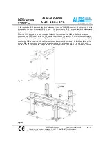
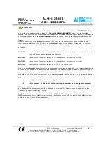
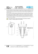
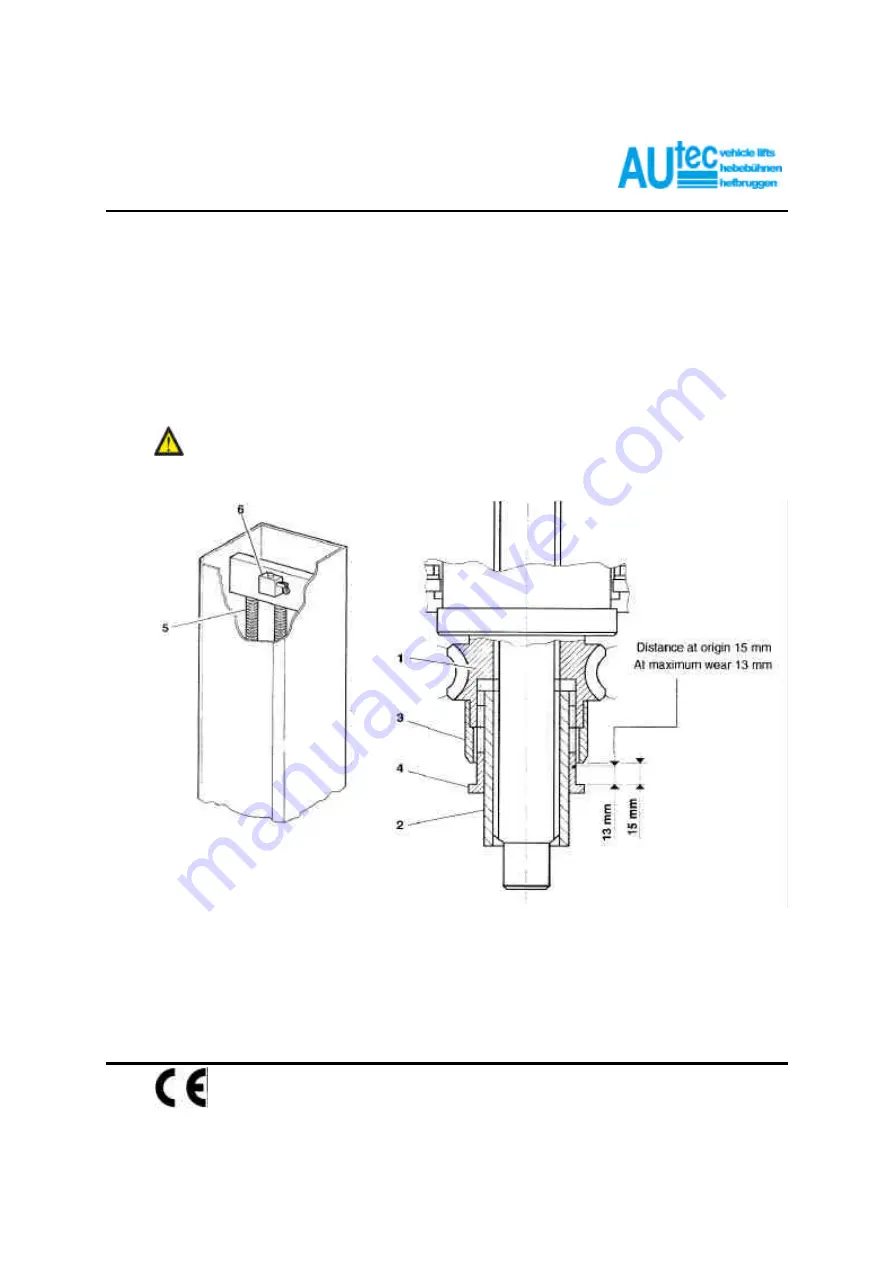
You will now be able to see the load-bearing support screw
(1)
and the safety counter screw
(2)
, with the bush
(3)
and the ring
(4)
on their respective outsides. The distance between bush
(3)
and ring
(4)
is set at 15 mm
initially and since the maximum permitted wear of the thread of the load-bearing support screw
(1)
is 1.8 mm,
a check should be made every six months to see that the minimum distance between rings
(3)
and
(4)
is not
less than 13.2 mm.
If this is the case, the load-bearing support screw
(1)
should be replaced as the thread is almost completely
worn. If this check is not done, the thread of the load-bearing support screw
(1)
will wear through completely
and the load will fall onto the counter screw
(2)
(max. stroke 10 mm). The load resting on the counter screw
(2)
will unbalance the screws
(5)
which, through the swing support to which they are attached, activate the
halt command
(6)
to stop the lift immediately. If this happens, the lift may only descend and will not start up
again once it has reached the ground. To restart the lift replace the load-bearing supportscrew (1). When dis-
mantling the gear box to replace one of the two support screws
(1)
changing both screws is recommended since
it will soon require replacing anyway.
When replacing the main nuts, check the integrity of the obstacle microswitch
(see para. 5-4) and again adjust the cam distance.


