en/TA-11-ALM-6040/10040FL
pag.: 27
USER /
INSTALATION
MANUAL
4-POST HD
ISSUED 26-05-04
A L M - 6 0 4 0 F L
A L M - 1 0 0 4 0 F L
AUTEC Hefbruggen bv
Industrieterrein IJsselveld, Vlasakker 11, 3417 XT MONTFOORT, The Netherlands
Tel: +31 348 477000 Fax: +31 348 475104 Internet: www.autec.nl - E-mail: [email protected]
W A R N I N G
Any connecting and disconnecting of electrical wires must always be done with the power
SWITCHED OFF
, in
other words with main switch in position “0”.
The NUMBERS SHOULD MATCH
exacly, both in the voltage
change in the motors and in connecting the terminals of the derivation boxes. During the test of lift operation, if
no movement occurs when the
RISE
or
DESCENT
button is pressed, although the teleswitch is activated and
the motors vibrate without turning, it means that two motors are wrongly connected. In this case proceed as
follows:
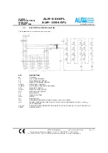
Open the control box using the appropriate key. Check that the wire numbers correspond to those on the
terminal board and these of the derivation boxes and motor boxes. If the numbers correspond, one or more
motors are connected wrongly in the terminal boards. To identify this, check individual motor rotation direction
as follows:
MOTOR 1
Disconnect the fuses from motors no. 2-3-4. Press the rise button to check that the lift rises and
press the descent button to check that it lowers.
MOTOR 2
Disconnect the fuses from motors no. 1-3-4 and check that it operates correcly.
MOTOR 3
Disconnect the fuses from motors no. 1-2-4 and check that it operates correctly.
MOTOR 4
Disconnect the fuses from motors no. 1-2-3, and repeat the test.
When you have identified the motor turning in the wrong direction, invert two wires in the motor terminal board.
At this point you should make a complete rise and descent run with the lift fully unloaded to check that it oper-
ates correctly with all four motors. If just one motor is turning in the wrong direction, it would be over-ridden by
the other 3 but it would cause the lift to halt within 30-40 seconds because of the disconnection of the tempera-
ture relay of the motor with incorrect rotation. At this point you may identify the motor by its excessive heating.
N.B.
Any variations to the connections must always be followed by adjusting the numbers correctly to facili-
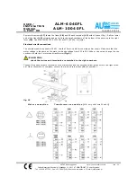
tate repair. For motor rotation direction, see fig. 11.
5 . 3
A d j u s t m e n t o f t h e d e v i c e c o n t r o l l i n g t h e w e a r o f t h e s u p p o r t s c r e w
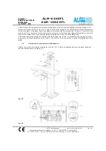
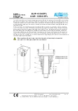
If the post support bases are not flat, and at the same level (max. permitted difference is 20 mm), there could
be variations at the swing supports
(39)
which held the screws
(41)
. This may cause an unbalance of the
“load-bearing support screw wear” control.
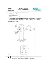
Since these levels are not easily obtained, we recommend you to make the following check: press the rise but-
ton
(22)
to lift the upper plane of footboards
(7)
and
(8)
600-700 mm from the ground and loosen the screws
(37)
to remove the covers
(36)
from all four posts. Remove the screws
(17)
to free the flaps
(18)
turn them
upside down and let each fall behind its post.


