Options :
- AV / BNC
- Touchscreen
- DC power
- DVI
- Audio in
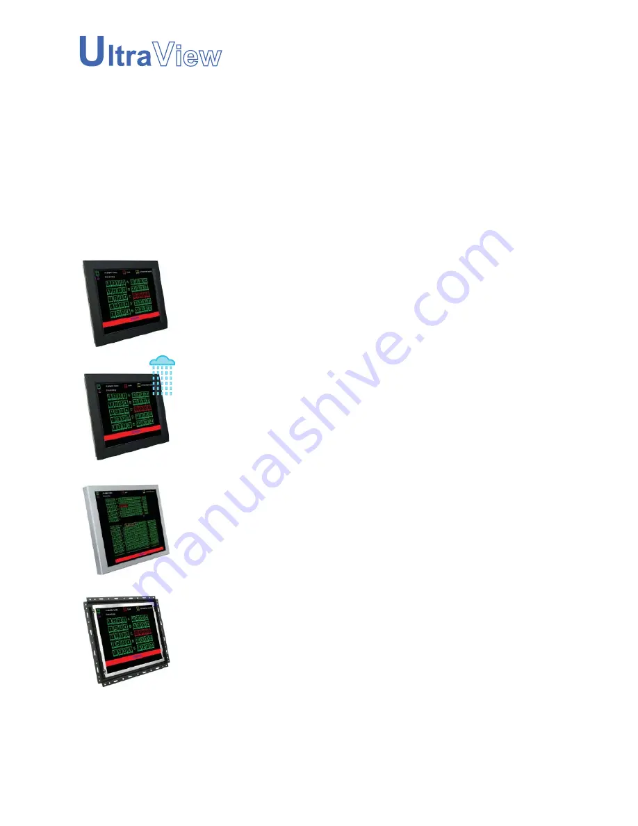
OP-17
Open frame LCD panel
AP-17
Front aluminum LCD panel
DP-17
Stylish front aluminum cover LCD panel
NAP-17
Front NEMA4 / IP 65 LCD panel
Innovative LCD Display
User Manual
17" LCD
Page 1: ...C Touchscreen DC power DVI Audio in OP 17 Open frame LCD panel AP 17 Front aluminum LCD panel DP 17 Stylish front aluminum cover LCD panel NAP 17 Front NEMA4 IP 65 LCD panel Innovative LCD Display User Manual 17 LCD ...
Page 2: ...ounting Method 6 7 Chapter 3 NAP 17 Front NEMA4 IP 65 LCD panel 3 1 Package Contents 8 3 2 Structure Diagram 9 3 3 Dimension Diagram 10 3 4 Mounting Method 11 12 Chapter 4 DP 17 Stylish front aluminum cover LCD panel 4 1 Package Contents 13 4 2 Structure Diagram 14 4 3 Dimension Diagram 15 4 4 Mounting Method 16 Chapter 5 OP 17 Open frame LCD panel 5 1 Package Contents 17 5 2 Structure Diagram 18 ...
Page 3: ...C DVI Options 9 1 DVI DOption 24 9 2 S Video RCA Input Option 24 9 3 S Video BNC Input Option 24 9 4 On screen Menu for DVI BNC S Video RCA Input 25 Chapter 10 Touchscreen Options 10 1 Touchscreen Quick User Guidelines 26 27 Chapter 11 DC Power Options 28 Chapter 12 Troubleshooting 29 Chapter 13 Dimensions 30 Chapter 14 Cleaning the LCD display 31 ...
Page 4: ...Blank page ...
Page 5: ...ire water lightning or other acts of nature unauthorized product modifi cation or failure to follow instructions supplied with the product Repair or attempted repair by anyone not authorized by us Any damage of the product due to shipment Removal or installation of the product Causes external to the product such as electric power fluctuation or failure Use of supplies or parts not meeting our spec...
Page 6: ...ion Convenience for connecting the LCD Display to the related facilities should be well considers too The LCD Display comes with the standard parts shown on the package contents Check and make sure they are in cluded and in good condition If anything is missing or damage contact the supplier immediately 1 3 Unpacking 1 2 Before Installation Chapter 1 P 2 1 Power Cord 1 1 IEC power cord 1 2 NEMA 5 ...
Page 7: ...pc User manual x 1 pc Power cord x 1 pc Auto switch power adapter x 1pc Mounting bracket A x 4 pcs Mounting bracket B x 12 pcs M4 6mm screw x 8 pcs M4 50mm screw x 12 pcs 5 4 2 1 3 User Manual 1 5 4 3 2 7 9 6 8 8 6 7 9 Remarks AP Series mounting bracket set includes item 6 9 please refer to p 6 7 ...
Page 8: ...P 4 2 2 AP 17 series Structure Diagram Chapter 2 5 1 2 3 Front View Rear View 4 Rear case SAMSUNG Class A TFT LCD panel 4mm protective glass 1 2 6mm aluminum front bezel LCD membrane 4 5 3 ...
Page 9: ...2 3 AP 17 series Dimension Diagram Chapter 2 Front View Rear View P 5 UNIT mm 1mm 0 03937 inch ...
Page 10: ...2 4 AP 17 series Mounting Method Chapter 2 1 4 3 2 Mounting bracket A x 4 pcs x 12 pcs x 8 pcs x 12 pcs Mounting bracket B P 6 M4 6mm screw M4 50mm screw Mounting bracket A Mounting bracket B ...
Page 11: ...2 4 AP 17 series Mounting Method Chapter 2 100mm VESA standard P 7 Remarks Hardware and M4 4 pcs for VESA mounting is not provided UNIT mm 1mm 0 03937 inch ...
Page 12: ...item 6 9 please refer to p 11 12 LCD display x 1 pc 6 VGA cable male to male x 1 pc User manual x 1 pc Power cord x 1 pc Auto switch power adapter x 1pc Mounting bracket A x 4 pcs Mounting bracket B x 12 pcs M4 6mm screw x 8 pcs M4 50mm screw x 12 pcs 5 4 2 1 3 User Manual 1 5 4 3 2 7 9 6 8 8 6 7 9 ...
Page 13: ...NAP 17 series Structure Diagram Chapter 3 5 1 2 3 Front View Rear View 4 Rear case SAMSUNG Class A TFT LCD panel 4mm protective glass Front NEMA 4 IP65 protection 1 2 6mm aluminum front bezel LCD membrane 4 5 3 ...
Page 14: ...3 3 NAP 17 series Dimension Diagram Chapter 3 P 10 Front View Rear View UNIT mm 1mm 0 03937 inch ...
Page 15: ...3 4 NAP 17 series Mounting Method Chapter 3 P 11 1 4 3 2 Mounting bracket A x 4 pcs x 12 pcs x 8 pcs x 12 pcs Mounting bracket B M4 6mm screw M4 50mm screw Mounting bracket A Mounting bracket B ...
Page 16: ...3 4 NAP 17 series Mounting Method Chapter 3 P 12 100mm VESA standard Remarks Hardware and M4 4 pcs for VESA mounting is not provided UNIT mm 1mm 0 03937 inch ...
Page 17: ...4 1 DP 17 series Package Contents Chapter 4 P 13 LCD display x 1 pc 6 VGA cable male to male x 1 pc User manual x 1 pc Power cord x 1 pc Auto switch power adapter x 1pc 5 4 2 1 3 User Manual 1 5 4 3 2 ...
Page 18: ...P 14 5 4 2 DP 17 series Structure Diagram Chapter 4 1 2 3 Front View Rear View 4 Rear case SAMSUNG Class A TFT LCD panel 4mm protective glass 1 2 1 2mm front aluminum cover LCD membrane 4 5 3 ...
Page 19: ...4 3 DP 17 series Dimension Diagram Chapter 4 Front View Rear View P 15 UNIT mm 1mm 0 03937 inch ...
Page 20: ...100mm VESA standard P 16 4 4 DP 17 series Mounting method Chapter 4 Remarks Hardware and M4 4 pcs for VESA mounting is not provided UNIT mm 1mm 0 03937 inch ...
Page 21: ...5 1 OP 17 series Package Contents Chapter 5 P 17 LCD display x 1 pc 6 VGA cable male to male x 1 pc User manual x 1 pc Power cord x 1 pc Auto switch power adapter x 1pc 5 4 2 1 3 User Manual 1 5 4 3 2 ...
Page 22: ...P 18 5 2 OP 17 series Structure Diagram Chapter 5 4 1 2 Front View Rear View Rear case SAMSUNG Class A TFT LCD panel 1 2 Universal open frame mounting LCD membrane 3 3 4 ...
Page 23: ...5 3 OP 17 series Dimension Diagram Chapter 5 Front View Rear View P 19 UNIT mm 1mm 0 03937 inch ...
Page 24: ...ounting P 20 Remarks Hardware for fixing the LCD display is not provided 5 4 OP 17 series Mounting method Chapter 5 100mm VESA standard Remarks Hardware and M4 4 pcs for VESA mounting is not provided UNIT mm 1mm 0 03937 inch ...
Page 25: ...wer to all devices before connecting them Apply power to connected devices again only after the LCD Display re ceiving power The company is not responsible for damage caused in this way Power 7 1 On screen Display Operation Chapter 7 Exit the OSD screen Shortcut key to auto adjustment by pressed the button for 5 seconds or Toggle analog digital video connection DVI D and video options only Scrolls...
Page 26: ...ock To enter into the phase clock sub menu H V POSITION H V Position Align the screen image left or right and up or down MISC Information Display the current resolution refresh rate and frequency information on the screen OSD Timer Set the time duration in seconds that the OSD is visible after the last button is pressed The factory default is 10 seconds Color Select the screen color 5500K 6500K 95...
Page 27: ...to sensing 100 to 240VAC 50 60Hz Power Consumption Max 40 Watt Standby 5 Watt Compatibility Multi platform Mix PCs SUNs IBMs HPs DELLs Options Graphic Input DVI D BNC S Video RCA video input DC Power DC power input with 12V 24V 48V selection Touchscreen Resistive and capacitive Environmental Operation 0 to 50 C Degree Storage 5 to 65 C Degree Relative Humidity 5 90 non condensing Shock 10G acceler...
Page 28: ...ncludes with a 6 DVI D cable 9 2 S Video RCA Input Option Remarks Package includes an extra 6ft S Video and 6ft RCA cables VGA Power S Video VGA Power 9 3 S Video BNC Input Option Remarks Package includes an extra 6ft S Video cable VGA Power RCA S Video BNC ...
Page 29: ... image left or right V Position Align the screen image up or down Clock Adjust the clock value Phase Aldjust the phase value 3 Function OSD Position Adjust OSD menu horizontal and vertical position OSD Zoom Adjust the difference between the image background black level and the foreground white level Color Temp Select the screen color 5500K 6500K 9500K The factory default is 6500 K 4 System Languag...
Page 30: ... the attached CD disc As the touchscreen unit is not made of toughened glass please handle it carefully USB VGA Power Serial VGA Power USB interface Serial interface Model 17TRB 17TRS Screen size 17 Interface USB serial Optical transmittance 82 5 Surface hardness 3H JIS K5400 Operating system Windows 98 2000 ME XP NT CE DOS Linux Model 17TCB_3M 17TCS_3M Screen size 17 Interface USB serial Optical ...
Page 31: ...ous records The record will bcome default record Press 25ptCal to do 25 points calibration Correct 25 point locations on screen with the panel Touch the blinking symbol on panel until beep or stop blinking After the calibration the new record will overwrite the old one Caution At the first assembly of touch screen we suggest applying 25 points calibration For a more accurate calibration of touch s...
Page 32: ...t 48 Volt Input range 9 18V 18 36V 36 75V Input current No load 50 mA 50mA 50 mA Full load 4950 mA 2450 mA 1220 mA Output rating Output voltage 12 Volt 12 Volt 12 Volt Output current 4 16A 4 16A 4 16A Efficiency 84 85 85 Remarks Package does not include power cord and AC power adapter VGA DC Power ...
Page 33: ...n image is not centered or sized properly Press the button for two seconds to automatically adjust the image Adjust the H position and V position settings via On screen menu 5 Must calibration be down after installation completed After connecting your touch monitor and installing the software you must calibrate the touchscreen Calibration serves two purposes A Set the active area of the touchscree...
Page 34: ...m 25 7 x 4 4 x 22 5 5 kg 12 1 lb 7 5 kg 16 5 lb NAP 17 series 438 x 59 x 363 mm 17 2 x 2 3 x 14 3 653 x 112 x 558 mm 25 7 x 4 4 x 22 5 5 kg 12 1 lb 7 5 kg 16 5 lb DP 17 series 393 x 52 x 311 mm 15 5 x 2 x 12 2 653 x 112 x 558 mm 25 7 x 4 4 x 22 5 5 kg 12 1 lb 7 5 kg 16 5 lb OP 17 series 416 x 50 x 334 mm 16 4 x 2 x 13 1 653 x 112 x 558 mm 25 7 x 4 4 x 22 5 5 kg 12 1 lb 7 5 kg 16 5 lb ...
Page 35: ...quid onto the screen directly 3 To remove dust and other particles wipe the screen with a clean soft lint free cloth 4 Be cautions of all kinds of cleaning solvents or chemicals some individuals may be harmful to the LCD display 5 If the LCD display is still not clean enough apply a small amount of non ammonia non alcohol based glass cleaner onto a clean soft lint free cloth and wipe the screen 6 ...
Page 36: ...cifications without prior notice and assumes no responsibility for any error which may appear in this publication All brand names logo and registered trademarks are properties of their respective owners Copyright 2007 Austin Hughes Electronics Ltd All rights reserved ...