background image


Survivable Branch Appliance 

AudioCodes Enhanced Media Gateway 

102 

Document #: LTRT-18206 

5.1.4 

Step 4: Configure Trunk Group Settings Table 

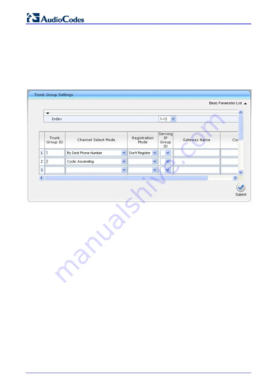
This step defines how to configure the method for which IP-to-Tel calls are assigned to channels 
within each Trunk Group. This is done in the 'Trunk Group Settings' page. 

¾


To configure the Trunk Group Settings table: 

1. 

Open the 'Trunk Group Settings' page (

Configuration

 tab > 

Protocol Configuration

 menu 

Trunk Group

 submenu > 

Trunk Group Settings

). 

Figure 


5-5: Trunk Group Setting Table Page 


2. 

Configure the Trunk Group according to the figure above: 


The Channel Select Mode of the FXS port (Trunk Group ID 1) should be set to ‘By Dest 
Phone Number’. 


The Channel Select Mode of the digital trunk should be set to ‘Cyclic Ascending’. 

Summary of Contents for Mediant 1000

Page 1: ...Media udioCod nd SBA allat 1000 nt 2000 des Enh for Mic tion 0 Medi 0 hanced crosoft and Man ant 100 d Media Lync d Co nual 00 MSB a Gatew onfig l BG way gura Vers Decem Docum tion sion mber 201 ment LT n 1 3 0 TRT 1820 06 ...

Page 2: ......

Page 3: ...33 2 2 3 2 Connecting the E1 T1 Trunk Interfaces 33 2 2 3 3 Connecting the Ethernet Interface 34 2 2 3 4 Connecting the Power Supply 35 2 2 3 4 1 Connecting the AC Power Supply 35 2 2 3 4 2 Connecting the DC Power Supply 36 3 Initialization 37 3 1 Assigning the Gateway an IP Address 37 3 1 1 Mediant 1000 37 3 1 1 1 Assigning an IP Address using HTTP 38 3 1 1 2 Assigning an IP Address using BootP 3...

Page 4: ...lan Notation 93 4 10 3 Numbering Plans and Type of Number 94 4 10 4 Number Normalization Examples 95 5 Connecting Analog Devices to Lync 2010 97 5 1 Enhanced Media Gateway Configuration 99 5 1 1 Step 1 Enable IP to IP Application 99 5 1 2 Step 2 Configure the Number of Media Channels 100 5 1 3 Step 3 Configure Trunk Group Table 101 5 1 4 Step 4 Configure Trunk Group Settings Table 102 5 1 5 Step 5...

Page 5: ...t Date and Time 132 6 2 2 5 Join to Domain 135 6 2 2 6 Device Preparation 138 6 2 2 7 Configuration 142 6 2 2 8 Enable Replication 144 6 2 2 9 Activate MCS 146 6 2 2 10 MCS Certificate 148 6 2 2 11 Start MCS Services 153 6 2 2 12 Gateway Configuration 154 6 2 2 13 OCS Test Call 156 6 2 2 14 Complete Setup 158 6 2 3 Home 160 6 2 4 Tools 160 6 2 5 Start and Stop Service 161 6 2 6 System Update 162 6...

Page 6: ... Power 32 Figure 2 23 50 pin Female Telco Board Mounted Connector 33 Figure 2 24 RJ 48c Connector Pinouts 34 Figure 2 25 RJ 45 Connector Pinouts 34 Figure 2 26 DC Power Terminal Block Screw Connector 36 Figure 2 27 DC Power Terminal Block Crimp Connector 36 Figure 3 1 Enter Network Password Screen 38 Figure 3 2 BootP Client Configuration Screen 39 Figure 3 3 Multiple Interface Table Page 43 Figure...

Page 7: ... AudioCodes Gateway 98 Figure 5 2 Applications Enabling Page 99 Figure 5 3 Admin Page for IP Media Channels Settings 100 Figure 5 4 Trunk Group Table Page 101 Figure 5 5 Trunk Group Setting Table Page 102 Figure 5 6 Trunk Setting Page 103 Figure 5 7 IP Group Table Page 104 Figure 5 8 IP Group Table Page 105 Figure 5 9 Proxy Sets Table Page 106 Figure 5 10 IP to Trunk Group Routing Page 107 Figure ...

Page 8: ... PM Install MediationServer ini 140 Figure 6 50 Device Preparation Completion 141 Figure 6 51 Configuration 142 Figure 6 52 Configuration Start 142 Figure 6 53 Configuration Completion 143 Figure 6 54 Enable Replication 144 Figure 6 55 Enable Replication 144 Figure 6 56 Enable Replication Completion 145 Figure 6 57 Activate MCS 146 Figure 6 58 Activate MCS Processing 146 Figure 6 59 Activate MCS C...

Page 9: ...Descriptions 18 Table 2 3 OSN3 Specifications 19 Table 2 4 OSN3 Module Component Description 19 Table 2 5 Gigabit Ethernet Interface RJ 45 Connector Pinouts 20 Table 2 6 RS 232 Serial Interface Connector Pinouts 20 Table 2 7 OSN3 Module LED Description 21 Table 2 8 HDMX Module LED Description 22 Table 2 9 E1 T1 Connector Pinouts for Each 50 pin Telco Connector 33 Table 3 1 Default IP Addresses 37 ...

Page 10: ...Survivable Branch Appliance AudioCodes Enhanced Media Gateway 10 Document LTRT 18206 Reader s Notes ...

Page 11: ... 000 Median 11 Notice n and confi osoft Lync believed to be ements and e Published ent and udioCodes L subject to ch ished Decem ito CTI2 C MediaPack VMAS Voic VoIP and 3G cts or tradem electronic a local recycli vice are prov as purchased pport audio sed is spelle this manual the term Me nt 1000 MSB iguration of Server 20 e accurate a revisions Au nor can it a other docu Ltd All right hange witho...

Page 12: ...Survivable Branch Appliance AudioCodes Enhanced Media Gateway 12 Document LTRT 18206 Reader s Notes ...

Page 13: ...r Mediation Server The Mediation Server can be deployed either on a standalone physical server or co located with the Front End server pool The latter is a new enhancement in Lync Server 2010 The Mediation Server is the Lync Server 2010 edge entity responsible for interfacing the Lync Server 2010 network with an Enhanced Media Gateway that provides legacy connections to the PSTN This solution is c...

Page 14: ...and collaboration needs and hence are vulnerable to losing communication capabilities when the WAN is unavailable Given the always available expectation for voice it is imperative that the UC solution continues to provide the ability for branch users to make and receive calls when the WAN from the branch to the primary data center is unavailable To provide basic voice services to branch users duri...

Page 15: ... SBA application is located at the enterprise s branch office The hosting method for the SBA application depends on the Media Gateway Mediant 1000 and Mediant 1000 MSBG hosted on the OSN3 Server platform Mediant 2000 hosted on the Single Board Computer SBC blade Figure 1 3 AudioCodes SBA Media Gateway Solution at Branch Office ...

Page 16: ...ep red analog d s a descriptio Figure 1 4 C Section 2 Section 3 n 3 2 1 16 cument ep procedure pliance SBA environmen lies to Audi ater following sec are installatio a Gateways ialize the Me erver hosting p procedures r p procedures evices on for configu Configuratio 1 2 1 2 Se Se es for config A application t ioCodes Me ctions on of AudioC edia Gateway g the SBA ap s for configu s for configur ur...

Page 17: ...h dual SATA hard disk drives HDD Note Any usage of additional AMC modules that are not described or mentioned in this document requires approval by AudioCodes 2 1 1 Physical Description This section provides a physical description of the Mediant 1000 2 1 1 1 Front Panel Description The Mediant 1000B chassis front panel is displayed in the figure below and described in Table 2 1 Figure 2 1 Front Pa...

Page 18: ...nd described in Table 2 2 Figure 2 2 Rear Panel Components Table 2 2 Rear Panel Component Descriptions Item Label Description 1 Protective earthing screw 2 ESD Electrostatic Discharge ESD socket 3 100 240V 1A Dual AC Power Supply Entries 4 OSN3 OSN3 AMC module 5 HDD Main Hard disk drive HDD AMC module for OSN3 platform 6 HDD Second optional HDD for OSN3 platform 7 Empty AMC module slots ...

Page 19: ...0 Chipset 64 bit RAM Memory 2 G or 4 G DDR2 with ECC Storage Single or Dual hard disk drive of 80 G SATA Bus Chipset 64 Bit L2 Cache 2 M Interfaces Gigabit Ethernet USB 2 0 via Connection Module RS 232 COM 2 1 1 3 1 OSN3 Module The OSN3 module connector ports are shown in the figure below and described in Table 2 4 Figure 2 3 OSN3 Module Ports Table 2 4 OSN3 Module Component Description Item Descr...

Page 20: ... I O BI_DC 5 I O BI_DC 6 I Rx I O BI_DB 7 I O BI_DD 8 I O BI_DD Serial cabling uses an RJ 45 to DB 9 female cable adapter supplied as shown below Figure 2 4 RJ 45 to DB 9 Serial Cable Adapter The RJ 45 connector pinouts for RS 232 interface are listed in the table below Table 2 6 RS 232 Serial Interface Connector Pinouts RJ 45 DB 9 Pin Signal Function Pin 1 RTS Request to send 8 2 DTR Data termina...

Page 21: ...er failure Flashing Processor over temperature above 125 C and processor over temperature above 100 C Off Normal operation 3 Red On When lit during boot up indicates clock failure Flashing Processor over temperature above 125 C and chipset over temperature above 105 C Off Normal operation 4 Red On When lit during boot up indicates a hardware reset Flashing Processor over temperature above 125 C Of...

Page 22: ...rily off if network packets are being sent or received through the RJ 45 port When this LED remains off a valid link has not been established due to a missing or a faulty cable connection 2 1 1 3 2 HDMX Hard Disk Drive Module The components of the HDMX module is shown in the figure below and described in Table 2 7 Figure 2 6 HDMX Module Components Table 2 8 HDMX Module LED Description Item Color S...

Page 23: ...e connector located on the backplane 2 Connect all external interfacing cables to the module as required 3 Using the handle on the front panel engage the module with the chassis backplane 4 When the handle is locked the module is engaged the HS LED turns off The following procedure describes how to extract an AMC module from the chassis Note Before extracting the HDMX module if required you must p...

Page 24: ... be in accordance with the regulations enforced in the country of installation Figure 2 8 Earthing the Device 2 1 2 2 Connecting to Network The connection to the network depends on the module housed in the device s chassis CMX refer to Section 2 1 2 2 1 CRMX refer to Section 2 1 2 2 2 2 1 2 2 1 CMX Module The device s CPU module provides two 10 100Base TX RJ 45 ports for connectivity to the Ethern...

Page 25: ...ted pair copper cabling providing 1 Gigabit Ethernet GbE interface for connection to the Internet CRMX S 1000Base SX optical multi mode fiber port CRMX L 1000Base LX optical single mode fiber port CRMX T RJ 48c 2 twisted pairs copper cabling Channel Service Unit Data Service Unit DSU CSU T1 WAN port for connecting to a T1 line Gigabit Ethernet Copper Cabling The CRMX C module provides a 100 1000Ba...

Page 26: ...nimum 3 dBm maximum Connector LC type plug Caution Laser If the CRMX module s WAN port is ordered for optical fiber interface then the device is a Class 1 LED Laser emitting device as defined by 21CFR 1040 and IEC825 Do not stare directly into the beam or into fiber optic terminations as this can damage your eyesight Avoid exposure to laser radiation by ensuring that you insert dust EMI plugs into...

Page 27: ...vides a WAN connection through a T1 line interface according to ANSI T1 403 1999 The module s T1 WAN DSU CSU port interface transmits and receives 1 544 Mbps data using IP over Point to Point Protocol PPP or IP over High Level Data Link Control HDLC framing Warning To protect against electrical shock and fire use a 26 AWG min wire to connect the T1 WAN port To connect the device s T1 WAN DSU CSU p...

Page 28: ... FXS FXO Interfaces The procedure below describes the cabling of the device s FXS and FXO module analog interfaces Warnings To protect against electrical shock and fire use a 26 AWG min wire to connect FXO ports to the PSTN Ensure that FXS and FXO ports are connected to the appropriate external devices otherwise damage to the device can occur To connect the FXS FXO interfaces Using the device s RJ...

Page 29: ...power supply modules Power 1 and Power 2 each providing an AC power connector on the device s rear panel The dual power option provides the device with power redundancy Warnings Units must be connected by service personnel to a socket outlet with a protective earthing connection Use only the AC power cord supplied with the device To connect the device to the power supply On the device s rear panel...

Page 30: ...evels on either side for inserting and removing the blade into and from the Mediant 2000 chassis front panel slot To remove the blade 1 Disconnect all cables from the blade 2 Unfasten the screws located at both ends of the blade which secure the blade to the chassis 3 Press the blade s red ejector buttons located on each of the two black ejector injector levers 4 Pull the two ejector injector leve...

Page 31: ... for Microsoft Lync 31 December 2010 4 Lock the blade into place by pressing the two black ejector injector levers on both ends inward until you hear a click 5 Fasten the screws on the front of the blade to secure the blade to the chassis Figure 2 20 Inserting Blade ...

Page 32: ...Interfaces on page 33 3 Connect the Ethernet interface refer to Connecting the Ethernet Interface on page 34 4 Connect the power supply refer to Connecting to the Power Supply on page 34 Once you have completed the above hardware installation steps after powering up the device the Ready and LAN LEDs on the front panel turn green after a self testing period of about three minutes Any malfunction ch...

Page 33: ...r devices with 16 spans or RJ 48c for devices with 1 2 4 or 8 spans connectors To connect E1 T1 trunks using 50 pin Telco connectors 16 trunk device 1 Attach the Trunk cable s of at least 26 AWG UTP 50 pin male Telco connector to the 50 pin female Telco port labeled TRUNKS 1 8 on the device s rear panel 2 Connect the other end of the Trunk cable to the PBX PSTN switch 3 Repeat steps 1 through 2 fo...

Page 34: ...nection to the Ethernet network The dual ports provide Ethernet redundancy To connect the Ethernet interface 1 Connect a standard Category 5 network cable to the Ethernet RJ 45 port labeled ETH on the device s rear panel 2 Connect the other end of the Category 5 network cable to your IP network 3 For Ethernet redundancy backup repeat steps 1 through 2 for the second Ethernet port The RJ 45 connect...

Page 35: ...arthed AC power supply 3 For connecting the second AC power socket if power supply redundancy is supported follow steps 1 through 2 but connect this second power cable to a separate earthed mains circuits Note For dual AC power supply please note the following The LED on the left side of the chassis only functions when the dual AC is used It is not relevant to the single AC power connection If onl...

Page 36: ...ed directly above each wire 2 Connect the two insulated wires to the correct DC power supply Ensure that the connections to the DC power supply maintain the correct polarity 3 Insert the terminal block into the DC inlet located on the device s rear panel Figure 2 26 DC Power Terminal Block Screw Connector To connect power using a DC terminal block crimp connector 1 Remove the DC adaptor screw conn...

Page 37: ...Default IP Addresses Parameter Default Value IP Address 10 1 10 10 Subnet Mask 255 255 0 0 Default Gateway IP Address 0 0 0 0 To assign an IP address to the device use one of the following methods Device s HTTP based embedded Web server accessed using a Web browser refer to Assigning an IP Address using HTTP on page 47 BootP refer to Assigning an IP Address using BootP on page 48 Voice Menu using ...

Page 38: ... the Uniform Resource Locator URL field enter the device s default IP address e g http 10 1 10 10 the Web interface s Enter Network Password dialog box appears as shown in the figure below Figure 3 1 Enter Network Password Screen b Enter the device s default login case sensitive user name Admin and password Admin and then click OK the Web interface is accessed displaying the Web interface s Home p...

Page 39: ... s MAC address The MAC address is printed on the label located on the underside of the device Ensure that the check box to the right of the field is selected this enables the client in the BootP tool if the client is disabled no replies are sent to BootP requests 6 In the IP field enter the IP address in dotted decimal notation that you want to assign to the device 7 In the Subnet field enter the ...

Page 40: ...to finish d Review the new subnet mask and then press 1 to save 6 To change the default Gateway IP address a Press 3 followed by the key The current default Gateway address is played b Press the key c Dial the new default Gateway address e g 192 168 0 1 and then press to finish d Review the new default Gateway address and then press 1 to save 7 Hang up the handset 8 Access the device s Web interfa...

Page 41: ...uration from the HTTP server The following is an example perl CGI script suitable for most Apache based HTTP servers for generating configuration dynamically per pattern 6 above Copy this script to var www cgi bin acconfig cgi on your Apache server and edit it as required usr bin perl use CGI query new CGI mac query param mac ip query param ip print Content type text plain n n print INI file gener...

Page 42: ...e Stop Bits 1 Flow Control None The CLI prompt appears 3 At the prompt type conf and then press Enter the configuration folder is accessed 4 To view the current network parameters at the prompt type GCP IP and then press Enter the current network settings are displayed 5 Change the network settings by typing the following SCP IP ip_address subnet_mask default_gateway For example SCP IP 10 13 77 7 ...

Page 43: ...e Configuration tab VoIP menu Network Settings IP Settings 2 Select the Index radio button corresponding to the Application Type OAMP Media Control i e VoIP and management interface and then click Edit 3 Configure the new IP address and prefix length so that it corresponds to your network IP addressing scheme e g 10 8 6 86 4 Configure additional IP interfaces if required Figure 3 3 Multiple Interf...

Page 44: ...e VoIP and Management interface To define the device s LAN data routing IP address 1 Access the device s Web interface with the IP address that you assigned to the VoIP and Management interface refer to VoIP and Management LAN Interface on page 43 2 Access the Connections page Configuration tab Data Settings menu Data System Connections Figure 3 4 Connections Page 3 Click the LAN Switch VLAN 1 con...

Page 45: ...5 Define the IP address pool using the fields under the IP Address Distribution group 6 Click OK 7 If required refresh the address by disconnecting the cable and then reconnecting it again or by performing the following in the Windows command line interface ipconfig release ipconfig renew 3 1 2 3 Assigning a WAN IP Address Once you have configured the device s LAN interfaces you can then define th...

Page 46: ...ab Data Settings menu WAN Access submenu Settings Figure 3 7 Configuring the DHCP Server 4 From the Connection Type drop down lists select the required connection type for the WAN and then configure the subsequent available fields for the selected connection type 5 Configure the WAN interface operating mode for Network Address Port Translation NAPT a Click the Click here for Advanced Settings link...

Page 47: ...using BootP on page 48 Embedded Command Line Interface CLI accessed using RS 232 if supported or Telnet refer to Assigning an IP Address using the CLI on page 50 Dynamic Host Control Protocol DHCP refer to the User s Manual Tip If at a later stage after re defining the IP address your IP address is unknown e g forgotten use the BootP TFTP utility to access the device refer to the Product Reference...

Page 48: ... the following a Open the Multiple Interface Table page Configuration tab Network Settings menu IP Settings b Define the device s IP address subnet mask and default Gateway IP address for OAMP Media Control application type so that they correspond to your network IP scheme c Click Apply d Save your settings to the flash memory and reset the device 5 When implementing a device with two modules repe...

Page 49: ...s printed on the label located on the underside of the device Ensure that the check box to the right of the field is selected this enables the client in the BootP tool if the client is disabled no replies are sent to BootP requests 6 In the IP field enter the IP address in dotted decimal notation that you want to assign to the device 7 In the Subnet field enter the subnet mask in dotted decimal no...

Page 50: ...ty None Stop Bits 1 Flow Control None The CLI prompt appears 3 At the prompt type conf and then press Enter the configuration folder is accessed 4 To view the current network parameters at the prompt type GCP IP and then press Enter the current network settings are displayed 5 Change the network settings by typing the following SCP IP ip_address subnet_mask default_gateway For example SCP IP 10 13...

Page 51: ...ensure that Remote Desktop is enabled The remote PC must be in the same subnet as the OSN server default IP address is 10 1 10 12 3 2 1 1 Cabling Before you can connect remotely to the OSN Server you need to cable a PC running Remote Desktop Connection to the OSN Server s IP network interface The OSN3 server connects initially to the IP network through the LAN port of the OSN3 module To cable OSN3...

Page 52: ...gram To remotely connect a PC to the OSN Server running Windows 1 Change the PC s IP address so that it is in the same subnet as the default OSN Server s IP address i e 10 1 10 12 The figure below displays an example of a changing a PC s IP address Figure 3 12 Changing the PC s IP Address 2 Start Microsoft s Remote Desktop Connection program from the Start menu point to Programs to Accessories to ...

Page 53: ...nter the OSN Server s default IP address i e 10 1 10 12 4 Click Connect Figure 3 14 Entering User Name and Password in Remote Desktop Connection 5 Enter the OSN Server s default user name i e Administrator and password i e Pass123 6 Click OK Remote Desktop Connection connects you to the desktop of the device s OSN server ...

Page 54: ... Mediant 1000 OSN server using the serial port 1 Connect one end of the serial cable refer to Section 2 1 1 3 1 to the OSN serial port and the other end to the PC serial port 2 Start HyperTerminal and set the port to 115200 bits per second 8 data bits N parity 1 stop bits the following prompt appears Figure 3 15 Terminal Prompt 3 At the prompt enter I to list all the IP network numbers and their I...

Page 55: ...s to the ade s RJ 45 igure 3 17 C 2000 Microso using the de ternative yo Desktop Co 2 24 55 performed t SBC blade r e Administr 00 SBC serv pter cable to sions to their nitor e mouse and port to your Cabling of t oft Windows efault user na ou can acce onnection p through the running Micr rator and pa ver the DB 26 m r respective i d keyboard network he SBC Bla Server 2008 ame Admin ess the SBC pro...

Page 56: ...Survivable Branch Appliance AudioCodes Enhanced Media Gateway 56 Document LTRT 18206 Reader s Notes ...

Page 57: ...edures figuring the nning SIP firm be installed g with Micros on StrongE sport type 0B MSBG o eature erver s I Server thro pecific to de ne calls PB dia Gateway s erver acts as n Server in th hieve the Lyn P address o page Confi n submenu 4 Config ced M for configu Gateway pl mware Versio with the follo soft Lync Encryption an or IP2IP for M IP Addr ough which eployment y BX PSTN and s embedded s ...

Page 58: ...Redundant Routing Mode drop down list select Proxy This parameter determines that if a 5xx response is received for an INVITE message to the primary proxy the Gateway will attempt to send it to the redundant proxy To configure 503 for the Reason for Alternative Routing as required by Lync 2010 refer to Section 4 2 4 Click Submit 5 Click the Proxy Set Table button to open the Proxy Sets Table page ...

Page 59: ...port type TCP or TLS according to your deployment For additional details for transport type configuration refer to the following sections For TLS Section 4 3 For TCP Section 4 4 8 From the Enable Proxy Keep Alive drop down list select Using OPTION to discover whether a particular Mediation Server in the cluster is available 9 If your environment has multiple Mediation Servers you need to configure...

Page 60: ... if the Mediation server appears in an administrative list under Dest IP Address in the Tel to IP Routing Table refer to the next step The IP Security parameter determines whether the device accepts sends SIP calls only from to the configured IP addresses defined in the Tel to IP Routing Table 14 Open the Tel to IP Routing Table page Configuration tab Protocol Configuration menu Routing Tables sub...

Page 61: ...rnative Routing for Tel to IP calls to be a 503 SIP response To define SIP Reason for Alternative Routing 1 Open the Reasons for Alternative Routing page Configuration tab Protocol Configuration menu Routing Tables submenu Reasons for Alternative Routing Figure 4 5 Reasons for Alternative Routing Page 2 Under the Tel to IP Reasons group for Reason 1 select 503 3 Click Submit 4 Open the Admin page ...

Page 62: ...ld enter the parameter FakeRetryAfter When the Gateway receives 503 without Retry After response header it will behave as if the 503 response includes a Retry After response header with the period specified by the parameter FakeRetryAfter 7 In the Enter Value field enter 60 8 Click Apply New Value 9 Save the changes to flash memory by clicking the Burn button on the toolbar ...

Page 63: ...ted signaling between Mediation Server and the Media Gateway which is connected to the PSTN If you configure your Media Gateway link for TLS then signaling of calls to and from the PSTN are encrypted end to end Transmission Control Protocol TCP In this transport type the SIP signaling between Mediation Server and the Media Gateway uses SIP over TCP which is unencrypted signaling If the SIP transpo...

Page 64: ...rs The procedure below configures general SIP parameters To configure general SIP parameters 1 Open the SIP General Parameters page Protocol Configuration Protocol Definition SIP General Parameters Figure 4 7 SIP General Parameters Page 2 From the SIP Transport Type drop down list select TLS 3 In the SIP TLS Local Port enter 5067 Corresponding to Mediation Server TLS transmitting port configuratio...

Page 65: ...pplication Settings page Network Settings Application Settings Figure 4 8 Application Settings Page 2 Define the NTP server s IP address so that it corresponds to your network environment 3 In the DNS Primary Server IP and DNS Secondary Server IP fields set the primary and secondary DNS server s IP addresses with the IP address of your DNS server 4 Click the Submit button to save your changes 5 Sa...

Page 66: ...es the Media Gateway name To configure the Media Gateway name 1 Open the Proxy Registration page Configuration tab Protocol Configuration menu Proxies IpGroups Registration submenu Proxy Registration Figure 4 9 Proxy Registration Page 2 In the Gateway Name field assign a unique FQDN name to the Media Gateway within the domain for example gw mcsw14 com 2 ...

Page 67: ...figure a certificate 1 Open the Certificates page Security Settings menu Certificates Figure 4 10 Certificates Page 2 In the Subject Name field enter the Media Gateway name as configured in the previous step refer to Section 4 3 3 and then click Generate CSR a Certificate request is generated 3 Copy the certificate from the line BEGIN CERTIFICATE to END CERTIFICATE REQUEST to a text file such as N...

Page 68: ...hanced Media Gateway 68 Document LTRT 18206 4 Navigate to the certificate Server http Certificate Server CertSrv Figure 4 11 Microsoft Certificate Services Web Page 5 Click the link Request a certificate Figure 4 12 Request a Certificate Page ...

Page 69: ...soft Lync 69 December 2010 6 Click the link advanced certificate request and then click Next Figure 4 13 Advanced Certificate Request Page 7 Click the link Submit a Certificate request by using base64 encoded and then click Next Figure 4 14 Submit a Certificate Request or Renewal Request Page ...

Page 70: ... PC 13 Navigate to the certificate Server http Certificate Server CertSrv 14 Click the link Download a CA Certificate Certificate Chain or CRL Figure 4 15 Download a CA Certificate Certificate Chain or CRL Page 15 Under the Encoding method group perform the following a Select the Base 64 encoding method option b Click the link Download CA certificate 16 Save the file as certroot cer in a folder on...

Page 71: ...ield click Browse and select the certroot cer certificate file that you saved on your local disk see Step 16 and then click Send File to upload the certificate Figure 4 16 Certificates Page 20 Save burn the Media Gateway configuration and reset the Media Gateway using the Web interface s Maintenance Actions page Management Configuration menu Maintenance Actions ...

Page 72: ...TTPS To define the cipher string for HTTPS 1 Open the Admin page by appending the case sensitive suffix AdminPage to the Media Gateway s IP address in your Web browser s URL field e g http 10 15 4 15 AdminPage Figure 4 17 Admin Page 2 On the left pane click ini Parameters 3 In the Parameter Name field enter the parameter HTTPSCipherString 4 In the Enter Value field enter ALL 5 Click Apply New Valu...

Page 73: ...ion Server to operate with TCP which is not recommended by Microsoft To define the SIP transport type for TCP 1 Open the SIP General Parameters page Configuration tab Protocol Configuration menu Protocol Definition submenu SIP General Parameters Figure 4 18 SIP General Parameters Page 2 From the SIP Transport Type drop down list select TCP 3 Click the Submit button to save your changes 4 Save the ...

Page 74: ...iation Server to use SRTP Required or Optional you need to configure the Media Gateway to operate in the same manner To configure the media security 1 Open the Media Security page Configuration tab Media Settings menu Media Security Figure 4 19 Media Security Page 2 From the Media Security drop down list select Enable to enable SRTP 3 From the Media Security Behavior drop down list select Mandator...

Page 75: ...enu Trunk Group Figure 4 20 Trunk Group Table Page 2 Configure the Trunk Group Table as follows a In the Module column select the module type i e FXS FXO BRI PRI for which you want to define the Trunk Group b In the From Trunk and To Trunk columns select the starting and the ending physical Trunk number in the Trunk Group Applicable only to PRI and BRI modules c In the Channel s column enter the M...

Page 76: ...Group settings 1 Open the Trunk Group Settings page Configuration tab Protocol Configuration menu Trunk Group submenu Trunk Group Settings Figure 4 21 Trunk Group Settings Page 2 In the Trunk Group ID column enter the Trunk Group ID that you want to configure 3 From the Channel Select Mode drop down list select the method for which IP to Tel calls are assigned to channels pertaining to the Trunk G...

Page 77: ...7 roup Rou e Media Gat up routing Routing page nu IP to T o Trunk Gro ce IP addre ource phone ires that the e Mediation nfigure in the ers to avoid a 4 Config uting teway s IP to e Configura runk Group oup Routing ss of the M e number is Gateways m Server is list e Source IP A accepting ca guring the En o Trunk Grou ation tab P Routing Page ediation Ser routed to Tr must honor re ted in the allo A...

Page 78: ...onfigure the Trunk settings 1 Open the Trunk Settings page Configuration tab PSTN Settings menu Trunk Settings Figure 4 23 Trunk Settings Page On the top of the page a bar with Trunk number icons displays the status of each trunk according to the following color codes Grey Disabled Green Active Yellow RAI alarm Red LOS LOF alarm Blue AIS alarm Orange D channel alarm ISDN only ...

Page 79: ...ailable and can be modified 4 Configure the required trunk parameters 5 Click the Apply Trunk Settings button to apply the changes to the selected trunk or click Apply to All Trunks to apply the changes to all trunks the Stop Trunk button replaces Apply Trunk Settings and the Trunk Configuration State displays Active 6 Save burn the Media Gateway configuration and reset the Media Gateway using the...

Page 80: ...N line 3 Click Submit to save your changes 4 Save burn the Media Gateway configuration and reset the Media Gateway using the Web interface s Maintenance Actions page Management Configuration menu Maintenance Actions 4 6 6 Uploading CAS Files and Assigning to Trunks If your deployment supports Channel Associated Signaling CAS you need to upload the CAS configuration file from your PC to the Media G...

Page 81: ...dia Gateway Select the file and then click Open the file name and path appear in the field beside the Browse button 3 Click the Load File button corresponding to the CAS file field the file s loading takes effect on the fly 4 Save burn the Media Gateway configuration and reset the Media Gateway using the Web interface s Maintenance Actions page Management Configuration menu Maintenance Actions 5 O...

Page 82: ... CAS file and then click Stop Trunk to de activate the trunk 7 From the CAS Table drop down list select the CAS file that you uploaded to the Media Gateway 8 Click Apply Trunk Settings to apply the settings 9 Save burn the Media Gateway configuration and reset the Media Gateway using the Web interface s Maintenance Actions page Management Configuration menu Maintenance Actions ...

Page 83: ... page Configuration tab PSTN Settings menu Trunk Settings Figure 4 27 Trunk Settings Page 2 Click the Trunk icon pertaining to the trunk you want to configure and then click Stop Trunk to de activate the Trunk 3 From the ISDN Termination drop down list select whether the Trunk connected to the PBX is User or Network side 4 Click Apply Trunk Settings to apply the settings 5 Save burn the Media Gate...

Page 84: ...uppression to improve the performance of Mediation Server The procedure below shows how you can change the default coder To define the voice coder and silence suppression 1 Open the Coders page Configuration tab Protocol Configuration menu Coders And Profile Definition submenu Coders page item Figure 4 28 Coders Table Page 2 From the Coder Name drop down list select the required coder 3 From the S...

Page 85: ...may need to change the Media Gateway Silence Suppression Comfort Noise and Automatic Gain Control AGC parameters to achieve this goal Please note that the Echo canceller is enabled by default To configure silence suppression parameters 1 Silence Suppression is configured per coder type Refer to Section 4 7 above to enable Silence Suppression per coder 2 Open the RTP RTCP Settings page Configuratio...

Page 86: ...on tab Media Settings menu IPmedia Settings Figure 4 30 IPMedia Settings Page 6 From the Enable AGC drop down list select Enable 7 Click Submit 8 Open the IPMedia Settings page Configuration tab Media Settings menu IPMedia Settings page item 9 From the IPMedia Detectors drop down list select Enable Figure 4 31 IPMedia Settings 6 ...

Page 87: ...ngback tone generated by the call recipient s mobile phone This is also the case in team call scenarios where a call is routed to two team members one of whom has configured simultaneous ringing for his or her mobile phone According to Lync 2010 requirements the AudioCodes Media Gateway should send 183 with SDP immediately after it receives an INVITE The RTP packets however will not be sent until ...

Page 88: ...m the Play Ringback Tone to Tel drop down list select Play Local Until Remote Media Arrive If a SIP 180 response is received and the voice channel is already open due to a previous 183 early media response or due to an SDP in the current 180 response the Media Gateway plays a local ringback tone if there are no prior received RTP packets The Media Gateway stops playing the local ringback tone as s...

Page 89: ...h an SDP received thereafter 5 Click Submit to save your changes 6 Open the Admin page by appending the case sensitive suffix AdminPage to the Media Gateway s IP address in your Web browser s URL field e g http 10 15 4 15 AdminPage Figure 4 33 Admin Page Settings 7 In the Admin Page on the left pane click ini Parameters 8 In the Parameter Name field enter the parameter ENABLEEARLY183 9 In the Ente...

Page 90: ...Phone Number Manipulation Table for Tel to IP Calls For IP to Tel calls Destination Phone Number Manipulation Table for IP to Tel Calls Source Phone Number Manipulation Table for IP to Tel Calls Manipulation number configuration examples are provided for inbound and outbound calls in Section 4 10 4 To configure the Number Manipulation tables 1 Open the Number Manipulation page you want to configur...

Page 91: ...on page 93 Table 4 1 Number Manipulation Parameters Description Parameter Description Source Trunk Group The source Trunk Group 1 99 for Tel to IP calls To denote any Trunk Group leave this field empty Notes This parameter is available only in the Source Phone Number Manipulation Table for Tel IP Calls and Destination Phone Number Manipulation Table for Tel IP Calls pages For IP to IP call routing...

Page 92: ...t you want added to the front of the telephone number For example if you enter 9 and the phone number is 1234 the new number is 91234 Suffix to Add The number or string that you want added to the end of the telephone number For example if you enter 00 and the phone number is 1234 the new number is 123400 Number of Digits to Leave The number of digits that you want to retain from the right of the p...

Page 93: ...nge of numbers Note Range of letters is not supported 5551200 5551300 represents all numbers from 5551200 to 5551300 123 100 200 represents all numbers from 123100 to 123200 n m Represents multiple numbers Up to three digits can be used to denote each number 2 3 4 5 6 represents a one digit number that starts with 2 3 4 5 or 6 11 22 33 xxx represents a five digit number that starts 11 22 or 33 111...

Page 94: ...r in complete international E 164 format e g 16135551234 National 2 A public number in complete national E 164 format e g 6135551234 Subscriber 4 A public number in complete E 164 format representing a local subscriber e g 5551234 Private 9 Unknown 0 A private number but with no further information about the numbering plan Level 2 Regional 1 Level 1 Regional 2 A private number with a location e g ...

Page 95: ...e Media Gateway sends the number 95554321 to the PBX and then the PBX sends the number 5554321 to the PSTN 3 National calls to a different area code The caller dials 9 for an external line the out of area code and then a 7 digit telephone number e g 9 503 331 1425 Lync 2010 translates normalizes the phone number into an E 164 number format 15033311425 where 1 is the international code 503 the out ...

Page 96: ...user dials the national area code and then a 7 digit phone number e g 206 333 1220 which is received by the Media Gateway The Media Gateway s Manipulation table is configured to normalize the number into E 164 format and adds the prefix 1 to the number Therefore the Media Gateway sends the number 12063331220 to Lync 2010 which relays the call to the OC client Note Whether the area code is received...

Page 97: ...g of calls g devices or Server e Lync 2010 s or routed b es or to the P e calls to the call to vario such as fax r to the PSTN PSTN can be alog FXO c erve the ana analog FXS tic routing de way s interna resses s of impleme following ex Lync 2010 at AudioCodes eral trunks to ard that serv entities servi 5 Conn vices devices deplo s is performe r from the PS Front End s back to the c PSTN single cen...

Page 98: ...Survivable Branch Appliance AudioCodes Enhanced Media Gateway 98 Document LTRT 18206 Figure 5 1 Connecting Analog Devices in Lync 2010 Environment using AudioCodes Gateway ...

Page 99: ...ns Enabling abling Figure 5 2 P2IP Applicat ateway displays the Software Upg 99 eway Co section for im ways assum plication Media Gatew g page Con 2 Applicatio tion drop dow e application grade Key su 5 Conn onfigura mplementing mes the setup way s IP to IP nfiguration t ons Enabling wn list selec only if the M upporting the necting Analo ation g analog de p example ill P IP2IP app tab Protoc g Pa...

Page 100: ...media channels available on the Media Gateway is 120 i e up to 60 IP to IP calls To configure the number of the media channels 1 Open the Admin page by appending the case sensitive suffix AdminPage to the Media Gateway s IP address in your Web browser s URL field e g http 10 15 4 45 AdminPage Figure 5 3 Admin Page for IP Media Channels Settings 2 On the left pane click ini Parameters 3 In the Para...

Page 101: ...u to enable the device s channels by assigning them telephone numbers and other attributes e g Trunk Groups and Profiles To configure the Trunk Group table 1 Open the Trunk Group Table page Configuration tab Protocol Configuration menu Trunk Group submenu Trunk Group Figure 5 4 Trunk Group Table Page 2 Configure the Trunk Group according to the figure above To ensure correct routing of IP to Tel c...

Page 102: ...n the Trunk Group Settings page To configure the Trunk Group Settings table 1 Open the Trunk Group Settings page Configuration tab Protocol Configuration menu Trunk Group submenu Trunk Group Settings Figure 5 5 Trunk Group Setting Table Page 2 Configure the Trunk Group according to the figure above The Channel Select Mode of the FXS port Trunk Group ID 1 should be set to By Dest Phone Number The C...

Page 103: ...gure Trunk Settings This step describes how to configure the PBX PSTN Trunk that is connected to the Media Gateway To configure the Trunk Setting 1 Open the Trunk Settings page PSTN Settings menu Trunk Settings Figure 5 6 Trunk Setting Page 2 Use the page above to configure the Trunk parameters according to your PBX PSTN Trunk connection ...

Page 104: ... SRTP for security settings Therefore you must configure an IP Profile for the analog device which will disable the SRTP behavior in case the call should route to the ATA s device This IP Profile will be used later in the Routing table To configure the IP Profile settings 1 Open the IP Profile Settings page Configuration tab Protocol Configuration menu Coders And Profile Definition submenu IP Prof...

Page 105: ... Server To configure IP Groups 1 Open the IP Group Table page Configuration tab Protocol Configuration menu Proxies IpGroups Registration submenu IP Group Table Figure 5 8 IP Group Table Page 2 Define IP Group 1 for Mediation Server as follows Index 1 represent the ID for this IP Group Type SERVER used when the destination address configured by the Proxy Set in Step 7 Section 5 1 10 of the IP Grou...

Page 106: ...t Table e the Proxy S ng with the M age Config n submenu 5 9 Proxy S wn list selec n enter the p down list c type for th et to TLS th ication durin for configur Mediation ser Alive drop d when Mediatio g Method dr cing mechan Sets The Pro Mediation Se uration tab Proxy Sets Sets Table P ct 1 e IP addres correspondin he link betw he Media Ga ng the TLS h ring TLS tra rver down list sel on server re...

Page 107: ...nu IP to Trunk Group Routing Figure 5 10 IP to Trunk Group Routing Page 2 Configure the following routing rules Row 1 calls from source IP address 192 168 0 4 i e ATA 1 are assigned to Trunk Group ID 1 identifying them as inbound IP to IP calls These calls are later routed to the Mediation Server Section 5 1 14 Row 2 calls from source IP address 192 168 0 5 i e ATA 2 are assigned to Trunk Group ID...

Page 108: ...o I 5 11 Tel to rules urce IP Grou 2000 are rout Profile ID 1 urce IP Grou 2001 are rout Profile ID 1 s that do not s IP to IP ca o destination ateways mus ediation Serv P Routing T add the list outing ateway s Tel Configurat IP Routing IP Routing p up 1 i e Med ted to IP add p 1 i e Med ted to IP add t match the r alls and emb IP Group 1 st honor or se ver is in an Table Pleas of the truste Surv ...

Page 109: ...nfiguration tab Protocol Configuration menu Protocol Definition submenu SIP General Parameters Figure 5 12 SIP General Parameters Page 2 From the FAX Signaling Method drop down list select G 711 Transport 3 From Play Ringback Tone to IP drop down list select Play to provide a ringback tone to the analog device in case it transferred to another IP user 5 1 16 Step 11 Configure General Parameters Co...

Page 110: ...ces are AudioCodes MP 11x series the following configurations should be made 5 2 1 Step 1 Configure the Endpoint Phone Number Table The Endpoint Phone Number Table page allows you to activate the MP 11x ports endpoints by defining telephone numbers The configuration below uses the example of ATA1 destination phone number 17326522000 IP address 192 168 0 4 To configure the Endpoint Phone Number tab...

Page 111: ...odes central Media Gateway To configure the Tel to IP Routing table Open the Tel to IP Routing page Configuration tab Protocol Configuration menu Routing Tables submenu Tel to IP Routing Figure 5 14 Tel to IP Routing Page 5 2 3 Step 3 Configure Coders Table This step describes how to configure the coders for MP 11x To configure MP 11x coders Open the Coders page Configuration tab Protocol Configur...

Page 112: ...ers page Configuration tab Protocol Configuration menu Protocol Definition submenu SIP General Parameters Figure 5 16 SIP General Parameters Page 2 From the FAX Signaling Method drop down list select G 711 Transport 3 From the SIP Transport Type drop down list select TCP 4 In the SIP TCP Local Port field enter 5068 corresponding to the Central Gateway TLS transmitting port configuration 5 In the S...

Page 113: ...with Mic e SBA you m These step evice to the A count on the Technicians in Admin acc evice to your st calls from t CS works with In e Chrome compatibility w Settings s ebsites in Co server must u ve added 1 Compatib 6 Conf e Bran ion 1 the S A Media Gate s during a W ia Gateways the OSN serv crosoft Wind must perform ps contain the Active Directo Active Direc group This u count can pe topology the...

Page 114: ...t Technicians ent 114 e RC version e performed ch Applian anch Applian Appliance d 6 2 New Ob click Chang ain The bran stage or group tha up the prope Name to be le Branch Ap Appliance co dmins group on Active group Thi n For the Be at the datace nce Device nce device n evice name bject Comp ge to add a u ch site techn at is allowed rties for the S HOST SBA ppliance omputer obje p e Directory s us...

Page 115: ...y using Topology Builder and publish the topology To create branch sites 1 Open the Topology Builder Click Start All Programs Microsoft Lync Server 2010 RC and then click Lync Server Topology Builder Figure 6 3 Topology Builder Menu 2 On the screen below select Download Topology from existing deployment assuming your Lync Server deployment already has a topology a dialog to save the existing topol...

Page 116: ...ol By right clicking you can select the edit option for every section of the branch office If you did not use the planning tool right click the Branch Office Sites node and then click Define Branch Site Continue to the next step Figure 6 5 Lync Server 2010 Topology Builder 4 In the dialog box do the following Click Name and then type the name of the branch site Only this field is Required the othe...

Page 117: ...owing dialog box do the following Click City and then type the name of the city in which the branch site is located Click State Province and then type the name of the state or region in which the branch site is located Click Country Region Code and then type the two digit calling code for the country in which the branch site is located Click Next Figure 6 7 Specify Site Details ...

Page 118: ...n type the S Survivable B he same FQD SI edit above Figur 118 urvivable Br nish ne New Bra SBA FQDN Branch Appli DN as the S e re 6 9 Defin ranch Appli anch Site for ance the na urvivable Bra ne SBA FQD Surv D ance Wizar r Site Intero ame you ente anch Applian DN vivable Branc ocument L rd when thi p er in the Syst nce FQDN yo ch Appliance LTRT 18206 s wizard is tem FQDN ou entered e 6 s ...

Page 119: ...is SBA Figure 6 10 Front End Pool 9 Select the Edge Pool to be used with this SBA optional Figure 6 11 Edge Pool 10 Do the following Click Gateway FQDN op IP Address and then type the Gateway FQDN or IP to be used by the Mediation Server component of the SBA Click Listening port for IP PSTN Gateway and type the Gateway listening port Select the SIP Transport Protocol ...

Page 120: ...we strongly recommend that if you deploy a Survivable Branch Appliance that you use TLS Figure 6 12 Define the PSTN Gateway 12 Click Finish 13 Publish the new topology by right clicking on the root of the Lync Server 2010 RC menu bar and select the Publish Topology action Figure 6 13 Publish Topology Selection ...

Page 121: ...al 6 Configuring Survivable Branch Appliance SBA for Microsoft Lync 121 December 2010 14 Click Next Figure 6 14 Publish Topology Confirm Tasks 15 Confirm that all steps were succeeded and click Finish Figure 6 15 Publish Wizard Complete ...

Page 122: ...dministrat ew password 122 uring SB steps require Firefox Chr 10 1 10 12 appears e Login page message app ging in ecovered or m the DHCP Survivable B nistrator and tor password d instead of BA d to install a ome or Inte to start the e before the pear Refresh upgrade by and not 10 Branch Appl Password d was change the default P Surv D nd configure ernet Explor e SBA appl system is up h this page ti...

Page 123: ...d Configu crosoft Lync Note ration Manua Only a few al Fig w Setup men 123 gure 6 17 S u options are 6 Conf Setup Menu e active whe figuring Surv n first enterin vivable Branc Dec ng the applic ch Appliance cember 2010 cation e 0 ...

Page 124: ...e require Beta Refresh sh to provid DNS or set o 124 n are include e Setup men gs are describ d configuratio rmed correct uing with add nce to setup s and DNS S ttings the fo 18 Set IP Co sk and IP G ed to login ag h version pr de only one only one via ed in the foll nu options ar bed later in t on process to ly in sequen ditional tasks the SBA app ollowing scre onfiguration ateway field gain rovi...

Page 125: ...th Note ration Manua K the follow K he Username The syste al Figure 6 1 ing screen a Fig e Password m logs in wit 125 19 IP Settin appears gure 6 20 A and click Lo th the new IP 6 Conf ngs Login Alert Login ogin P address figuring Surv Again vivable Branc Dec ch Appliance cember 2010 e 0 ...

Page 126: ... Media Gatew As each m item way Figure menu item h Figure 6 22 126 6 21 Login has been co IP Settings Screen mpleted a g s Complete Surv D green check e vivable Branc ocument L k mark appe ch Appliance LTRT 18206 ars by the e 6 ...

Page 127: ...er name in use the sam ectory AD a r peration Co age also app e 6 24 Chan 127 uter name e Change Com Change Com n the Compu me Computer and on the T ompleted Su pears to adv nge Comput 6 Conf mputer Nam mputer Nam uter Name fi r Name which Topology on t uccessfully vise that a re ter Name R figuring Surv e link the fo me eld h was used f the pre confi message a boot is nece Reboot vivable Branc De...

Page 128: ...25 eboot the fo gain when th way click Reboot ot process c n appears 5 Change C ollowing scre Figure 6 2 he following s Figure 128 to restart the an take a few Computer Na een appears 26 Server R screen appe 6 27 Login e server w minutes ame Savin Re booting ars Screen Surv D ng Changes vivable Branc ocument L ch Appliance LTRT 18206 e 6 ...

Page 129: ...ion and Configuration Manual 6 Configuring Survivable Branch Appliance SBA for Microsoft Lync 129 December 2010 8 A green check mark appears by the completed menu item Figure 6 28 Change Computer Name Completed ...

Page 130: ...sword 1 On the Setup menu select the Change Admin Password link the following screen appears Figure 6 29 Set Local Administrator Password 2 In the Current Password field enter the current password 3 In the New Password field enter a new password 4 In the Password Confirm field enter the new password again 5 Click Apply the following screen appears Figure 6 30 Change Admin Password Saving Changes ...

Page 131: ...ion and Configuration Manual 6 Configuring Survivable Branch Appliance SBA for Microsoft Lync 131 December 2010 6 A green check mark appears by the completed menu item Figure 6 31 Change Admin Password Completed ...

Page 132: ...e Set Date and Time link the following screen appears Figure 6 32 Date Time Page 2 Select the Date tab and set the date and new time 3 Click Apply an Operation Completed Successfully message appears on the bottom of the screen 4 Click Time Zone tab the following screen appears Figure 6 33 Set Time Zone Page 5 Open the drop down list and select the appropriate Time Zone 6 Click Apply the following ...

Page 133: ...uring Survivable Branch Appliance SBA for Microsoft Lync 133 December 2010 Figure 6 34 Set Date and Time 7 The following confirmation screen appears Figure 6 35 Set Time Zone Page Confirmation 8 A green check mark appears by the completed menu item ...

Page 134: ...Survivable Branch Appliance AudioCodes Enhanced Media Gateway 134 Document LTRT 18206 Figure 6 36 Set Date and Time Completed ...

Page 135: ...oll K the follow Join to Do menu opti al es join to dom ain u click Join t Fig Name d Password owing scree Figure ing screen a omain requi on 135 main to Domain t gure 6 37 Jo of an accou n appears e 6 38 Join appears res a compu 6 Conf the following oin Domain unt that has Domain A uter re boot w figuring Surv g screen appe permissions lert which is done vivable Branc Dec ears s to join the e at ...

Page 136: ...g screen booting log The Doma in screen ap way e following s Figure 6 39 n appears Figure 6 4 in as the Do ain User che ppears Figure 6 136 screen 9 Join Dom 40 Server R main User ck box is sel 41 Welcom main Confir Re booting ected me to SBA Surv D rmation vivable Branc ocument L ch Appliance LTRT 18206 e 6 ...

Page 137: ...g in as th Figu n check mark The remai al he Domain U ure 6 42 Jo k appears by ining menu o 137 User the follo in to a Dom y the complet options now a 6 Conf owing screen ain Compl ted menu item appear in the figuring Surv n appears leted m e Setup men vivable Branc Dec nu ch Appliance cember 2010 e 0 ...

Page 138: ...6 6 2 2 6 Device Preparation This menu option completes the SQL preparation and installs the OCS components To prepare the device 1 On the Setup menu click Device Preparation the following screen appears Figure 6 43 Device Preparation 2 Click Apply Figure 6 44 Device Preparation Start ...

Page 139: ... 6 46 A Detailed the Detail al ns appear igure 6 45 D 6 Device Pre d Log can be ed Log link 139 Device Prep eparation e viewed afte to view the lo 6 Conf paration W PM Install O er each phase og figuring Surv ait Ocscore ms e has been c vivable Branc Dec i completed C ch Appliance cember 2010 Click on e 0 ...

Page 140: ...Enhanced Media Gateway 140 Document LTRT 18206 Figure 6 47 Device Preparation PM Install Server msi Figure 6 48 Device Preparation Restart 4 Click OK the following screen appears Figure 6 49 Device Preparation PM Install MediationServer ini ...

Page 141: ... compon k appears by e 6 50 Devi 141 been success h version ice preparat e Tools Men n steps have Apply on th nents y the complet ice Preparat 6 Conf sfully comple In case yo ion has finis nu or RDT e failed recti he Device Pre ted menu item tion Comp figuring Surv eted If not r u are not p shed you w fy the proble eparation pa m pletion vivable Branc Dec refer to the D rompted to will need to em ...

Page 142: ...creen way es a backup on u click Confi Fig figuration ste erver manua n appears Figure 142 copy of the guration th ure 6 51 Co ep fails imme ally using the e 6 52 Conf Central Man e following s onfiguration ediately after e Tools men figuration St Surv D nagement Se screen appea n r the Device u option tart vivable Branc ocument L erver to be s ars Preparation ch Appliance LTRT 18206 tored on the ...

Page 143: ...lation and Configuration Manual 6 Configuring Survivable Branch Appliance SBA for Microsoft Lync 143 December 2010 4 A green check mark appears by the completed menu item Figure 6 53 Configuration Completion ...

Page 144: ...8206 6 2 2 8 Enable Replication This menu option activates the replication process To enable replication 1 On the Setup menu click Enable Replication the following screen appears Figure 6 54 Enable Replication 2 Click Apply the following screen appears Figure 6 55 Enable Replication ...

Page 145: ...tion and Configuration Manual 6 Configuring Survivable Branch Appliance SBA for Microsoft Lync 145 December 2010 3 A green check mark appears by the completed menu item Figure 6 56 Enable Replication Completion ...

Page 146: ...e role Installing the required software does not automatically cause a computer to adopt a new service role instead that computer must be activated before it actually begins to function in its new role To activate MCS 1 On the Setup menu click Activate MCS the following screen appears Figure 6 57 Activate MCS 2 Click Apply the following screen appears Figure 6 58 Activate MCS Processing ...

Page 147: ...llation and Configuration Manual 6 Configuring Survivable Branch Appliance SBA for Microsoft Lync 147 December 2010 3 A green check mark appears by the completed menu item Figure 6 59 Activate MCS Completion ...

Page 148: ...icate the following screen appears Figure 6 60 Import Certification Certificates can be installed either by importing or requesting a certificate To import a certificate 1 Select the Import Certification radio button 2 Click Browse to select the File to Upload 3 Enter the Password optional of the certificates 4 Click Apply To request a certificate 1 Select the Request Certificate radio button Figu...

Page 149: ...eginning with a CA prefix are mandatory The correct Certificate Authority CA User and Password must also be supplied The CA field contains the CA FQDN CA Name Figure 6 62 MCS Certificate Detailed Log 3 If the CA field is not entered the system will create an enrollment certificate which can be downloaded Figure 6 63 MCS Certificate Download Enrolled Certificate 4 Click Apply the following screen a...

Page 150: ...es Enhanced Media Gateway 150 Document LTRT 18206 Figure 6 64 MCS Certificate Download Enrolled Certificate 5 Click the Download Enrolled Certificate link the following screen appears Figure 6 65 MCS Certificate File Download 6 Click Save ...

Page 151: ...nce the Enrollment Certificate has been signed select the Import Certification radio button as shown below and upload the signed certificate to be uploaded by using the Browse and File to Upload fields 8 Click Apply Figure 6 66 MCS Certificate File Upload 9 The following screen appears Figure 6 67 MCS Certificate Detail Log ...

Page 152: ...Survivable Branch Appliance AudioCodes Enhanced Media Gateway 152 Document LTRT 18206 10 A green check mark appears by the completed menu item Figure 6 68 MCS Certificate Complete ...

Page 153: ...o start a Microsoft Communications Server component that runs as a Windows service To start MCS Services 1 On the Setup menu click Start MCS Services the following screen appears Figure 6 69 Start MCS Services 2 Click Apply to start the services as per the MCS configuration settings 3 A green check mark appears by the completed menu item Figure 6 70 Start MCS Services Completion ...

Page 154: ...ick Gatew Figure 6 ateways de gateway is n IP Address setup the ga e 6 72 Gatew nt enable Te 154 y via its Web way Configu 6 71 Gatewa efault option not displayed s or DNS Nam ateway way Configu elnet b Administra uration the f ay Configur n select a ga d in the list me in the Ga uration Ma Surv D ator Telnet m following scr ration ateway from select the ateway field anual Gatew vivable Branc ocum...

Page 155: ... it in this step 73 Gatewa fails the pho at you can h en appears w appear 74 Gatewa 155 nstructions on default Port 2 bedded Teln not mandato p ay Configura one will not r hear the DTM when you an ay Configura 6 Conf n how to con 23 Refer to net Server to ory If you ch ation Test ring If the ph MFs nswer the ph ation Test figuring Surv nfigure the ga the Web Inte o Enable hanged the U t Call in Pr...

Page 156: ... o ings Note th kenmyer lit SIP addr toring setting SipUri sip jha ck Phone Nu ort eta Refresh 156 u to make a P must define for the cmdle in MCS and ration is setu ers for OcsH guration FirstTe g ame of the of the first te hat the SIP a twareinc com ress of the s gs Note that aas litwarei umber h version e PSTN call w special acco ets to run T they are voic up and the c HealthMonito Identity stUs...

Page 157: ...nstallation and Configuration Manual 6 Configuring Survivable Branch Appliance SBA for Microsoft Lync 157 December 2010 Figure 6 75 OCS Test Call 4 The following screen appears Figure 6 76 OCS Test Call ...

Page 158: ...y 158 Document LTRT 18206 6 2 2 14 Complete Setup 1 After completing all SBA settings click Complete When you log in the Home tab will be displayed and not Setup Figure 6 77 Complete Setup 2 The following screen appears Figure 6 78 Complete Setup Setup Completed ...

Page 159: ...nstallation and Configuration Manual 6 Configuring Survivable Branch Appliance SBA for Microsoft Lync 159 December 2010 3 A green check mark appears by the completed menu item Figure 6 79 Complete Setup ...

Page 160: ...d Media Gateway 160 Document LTRT 18206 6 2 3 Home The Home tab displays the Home page as shown below Figure 6 80 Home Page 6 2 4 Tools The Tools tab displays two sub menus Start and Stop Service System update as shown below Figure 6 81 Tools Page ...

Page 161: ...Lync 161 December 2010 6 2 5 Start and Stop Service The Start and Stop Service page appears as shown below Figure 6 82 Start and Stop Service Page Start All Starts the services on the SBA Stop All Stops the services on the SBA Restart Server Restarts the server Shutdown Server Shuts down the server ...

Page 162: ... Update menu provides the ability to Update the GUI software via a ZIP file Install an update as an MSU file from Microsoft To perform a system update 1 Click Browse and select the file to upload 2 Click Apply Figure 6 83 System Update Page 3 The following message appears Figure 6 84 System Logout Message 4 Click OK ...

Page 163: ...er 2010 5 The following message is displayed to inform you that you need to wait till the update has been completed Figure 6 85 Please Wait Message 6 The following Login page appears If you update the GUI software you will see the new version number on this login page Figure 6 86 Login Page with New Version Number ...

Page 164: ...r Event Viewer log as shown in the figure below Figure 6 87 Logs Page 1 To delete a log click on the event to view the detailed log section You can also clear or export the logs These two operations work only on the active log section Figure 6 88 Detailed Log Page 6 2 8 Logout The Logout option logs you out from the application ...

Page 165: ...as this functionality interfaces with only one Mediation Server which is co located on the same hardware chassis as the SBA Media Gateway Therefore follow the procedures in Section 4 but skip Step 9 of Section 4 1 b Exception 2 According to the SBA specification if the SBA application fails the SBA Media Gateway must switchover to the Mediation Server at the Data Center Therefore you should config...

Page 166: ...Document LTRT 18206 3 Open the Proxy Registration page Configuration tab Protocol Configuration menu Proxies IpGroups Registration submenu Proxy Registration and configure the Redundancy Mode parameter to Homing Figure 6 90 Defining Homing Mode for SBA Media Gateway 1 ...

Page 167: ...Installation and Configuration Manual 6 Configuring Survivable Branch Appliance SBA for Microsoft Lync 167 December 2010 Reader s Notes ...

Page 168: ...Installation and Configuration Manual Ver 1 3 www audiocodes com ...

Reviews: