

[
Description
]
The microphone features a 50' (15.2 m)
permanently-attached miniature cable. Its free
end connects to the provided AT8536 power
module via internal solderless screw terminals
for simple cable-length adjustment in the field.
It can be powered from any external 11V to 52V
DC phantom power supply. A recessed switch
in the power module permits choice of
flat response or low-frequency roll-off to help
control undesired ambient noise.
The microphone is enclosed in a rugged
housing with a low-reflectance black finish. It
is also available with white housing, cable and
hanger as the ES933W/C.
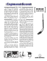
The ES933/C is a wide-range miniature
condenser microphone with a cardioid polar
pattern. It is designed for quality sound
reinforcement, professional recording, television
and other demanding sound pickup applications.
The ES933/C is furnished with a vinyl-coated
steel hanger that allows it to be adjusted for
correct positioning. An included snap-on foam
windscreen effectively reduces noise from wind
or ventilation air currents.
The cardioid polar pattern provides a 120°
angle of acceptance. Additional interchangeable
elements with hypercardioid (100°) and
MicroLine
®
(90°) pickup patterns are available.
E
ngineered
S
ound
is phased so that positive acoustic pressure
produces positive voltage at Pin 2, in accordance
with industry convention.
The cable length may be shortened at the
power module. To disassemble the power
module, turn the
silver
screw
counter-
clockwise
(left-handed thread) until it is down in
the connector base and clear of the case. Use a
screwdriver with
3
/
32
" (2.5 mm) blade. Then slide
the outer case up the cable to reveal the circuit
board and screw terminals. Loosen the three
terminal screws and remove the cable from the
module. Next, slide the case off the cable, cut the
cable to the desired length (allowing a few extra
inches) and slide the case back onto the cable.Tie
a single knot in the cable about two inches from
the cut end. Following Figure 3, cut the cable off
1" down from the top of the knot and carefully
remove
1
/
2
" of the outer jacket. Strip the mic
cable wires and attach them to their respective
terminals (Fig. 4). Make certain that the terminals
are clamped on the conductors, not on the
insulation, and that there are no loose strands of
wire which might touch other terminals. Replace
the case, being certain that the roll-off switch is
accessible and the silver screw is aligned with its
hole in the case. Finish by turning the screw
clockwise
until the case is firmly secured. Test
the microphone for proper operation.
While a modern condenser microphone
is not unduly sensitive to the environment, tem-
perature extremes can be harmful. Avoid leaving
the microphone in the open sun or in areas
where temperatures exceed 110° F (43° C) for
long periods of time. Extremely high humidity
should also be avoided.
The combination of small size and excellent
response makes the ES933/C ideal for
suspension over choirs, instrumental groups
or theater stages. A uniform 120° angle of
acceptance provides well-balanced audio pickup.
The microphone should be located forward of
the front-most source, above the rear-most
source, and “aimed” between them (Fig. 1).
Increasing the height of the mic above the
sources will tend to equalize sound levels
between them, but may also increase pickup of
background or reverberant sound. Whenever
possible, the distance from the mic to the
rear-most source should be no more than twice
the distance to the front source, to maintain
front-to-rear balance (Fig. 1).
Width of pickup is approximately three times
the distance to the closest performer. If
additional mics are needed for wide sources, they
should be positioned apart laterally at least three
times the distance to the front source, to avoid
phase cancellation (Fig. 2).
To orient the microphone in the proper
direction, twist the housing slightly in its
wire holder (clockwise rotation moves the
microphone to the right; counterclockwise
rotation moves it to the left).
The provided foam windscreen simply snaps
over the head of the microphone, effectively
reducing noise from wind or ventilation air
currents.
Output is low impedance balanced. The
output connector of the power module mates
with XLRF-type cable connectors. The balanced
signal appears across Pins 2 and 3, while the
ground (shield) connection is Pin 1. Output
[
Installation and Operation
]
[
[
ES933/C
Cardioid Condenser
Hanging Microphone
LESS THAN
2 TIMES “X”
DIST
ANCE “X”
120
°
ANGLE OF
ACCEPTANCE
Figure 1
MIC A
MIC B
3 TIMES
DISTANCE “X”
120
°
120
°
Figure 2
Shield strands,
fully twisted
Yellow-Yellow
Red-Red
1
/
8
" strip reds
and yellows
1
/
2
"
1"
Figure 3
Terminal
screws
Yellow-Yellow
Shield
Red-Red
PC board
+V
R
SIG
Y/W
GND
S
Figure 4


