7300 Industry Drive, North Little Rock, AR 72117
Phone: 501-955-2929 Fax: 501-955-2988
www.audiointl.com
Installation & Operation Manual
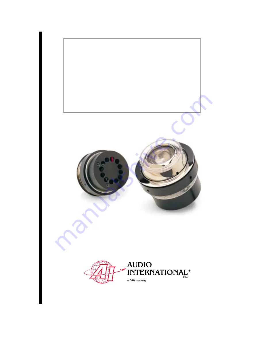
Model #: CL12/16W Series
12/16 Watt Cabin Light Assembly
Document #540037
Page 1: ...7300 Industry Drive North Little Rock AR 72117 Phone 501 955 2929 Fax 501 955 2988 www audiointl com Installation Operation Manual Model CL12 16W Series 12 16 Watt Cabin Light Assembly Document 540037...
Page 2: ...520368 Outline Drawing Cabin Light 12 16 Watt w internal fan Service Bulletin List Service Bulletin Subject Manual Revision Revision Date Table of Illustrations Illustration Description Page 1 Referen...
Page 3: ...5 2 0 Application 5 2 1 Introduction 5 3 0 Installation 6 3 1 Prior to Installation 6 3 2 Unpacking and Inspection 6 3 3 Cautions Warnings 7 3 4 Wiring Requirements 7 3 5 Physical Characteristics 7 3...
Page 4: ...y incorporated into new or existing lighting systems Refer to section 3 8 for specific model numbers and their descriptions 1 3 Operational Features Listed below are key features of the CL 12 16 Watt...
Page 5: ...The selected location must have an opening prepared for the unit to be inserted and mounted Refer to section 6 0 for unit dimensions and mounting hole locations 3 1 2 The CL 12 16 Watt Series Cabin Li...
Page 6: ...stallation of cable and connectors Avoid sharp bends and placing cables near aircraft control cables Maintain a minimum clearance of three 3 inches from any control cable If wiring is run parallel to...
Page 7: ...259F Female Screwlock P N M24308 26 1F DEMA 9S P N M24308 2 281F Male Screwlock 32 3 Pin Amp Receptacle P N 350767 1 Pin P N 350547 1 3 Pin Amp Plug P N 350766 1 Socket P N 350550 1 33 2 Pin Amp Plug...
Page 8: ...or 3 28 VDC 1 28 VDC 33 On Off only 2 Ground 1 28 VDC 2 Ground 3 BRT SW Input GND 4 DIM SW Input GND 51 2 Button Bright Dim Unit powers up at minimum brightness 5 28 VDC Emergency LTG Input 1 28 VDC 2...
Page 9: ...To verify power to the unit recheck 28 VDC is applied to the proper pins on the unit Use a voltmeter to verify correct level Reset by removing power from the unit for at least one minute and reapply p...
Page 10: ...es Cabin Light Installation Operations Document 540037 Rev B 4 2000 Page 10 of 11 7 0 Reference Drawings 7 1 Round Light Assembly The following diagrams show the unit dimensions of the round light ass...
Page 11: ...6 Watt Series Cabin Light Installation Operations Document 540037 Rev B 4 2000 Page 11 of 11 7 2 Square Light Assembly The following diagrams show the unit dimensions of the square light assembly All...