


FRONT PANEL LCD DISPLAY
4-2
TranScend Chassis – Operation Manual
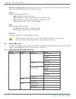
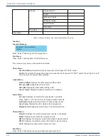
Multi-slot unit; Display avail on slot #:
this is the virtual slot on a multiple slot unit. User can access the module’s display
menu via the lowest slot of the multi slot unit. The slot # is shown.
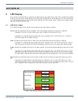
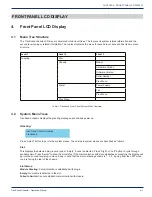
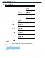
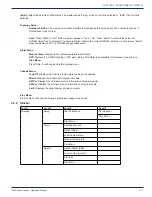
Chassis:
Displays all system related information.
Model:
Displays the chassis’ model name.
HW Ver:
Displays the hardware version information of TranScend chassis.
SW Ver:
Displays the software version information of TranScend chassis.
Ser #:
Displays the serial number of TranScend chassis.
Alarm:
Display all system related alarm status.
Pwr Sply:
displays the health of chassis power supply.
Fan:
displays the collective health of the chassis fans.
Prev Menu:
Press “Select” will bring the Greeting Message screen back.
NOTE: “Prev Menu” exists in all menu trees AT THE VERY BOTTOM. When you see it, place the
cursor on this line and press the “Select” button will go back to the previous menu.
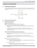
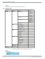
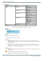
4.3 Plug-in Menu Tree
The plug-in menu displays is driven by the card type. Each model provides its own display structure. In any sub menu, press
“Select” on the
Prev Menu
line to return to the previous menu one level up.
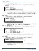
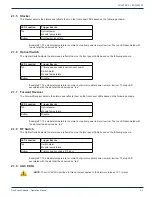
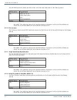
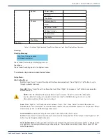
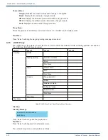
4.3.1 High Sensitivity Quad Return Receiver
Level 1
Level 2
Level 3
Level 4
Greeting
Setup
Attn Setting
Select Channel
Attn (dB)
Save
Prev Menu
Test Point
Select Channel
Prev Menu
Alarm Enable
Channel
Enable
Save
Prev Menu
Prev Menu
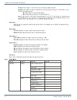
Status
Optical
Prev Menu
Alarm
Receiver Power
Module Temp
Prev Menu
CHAPTER 4:


