background image

LTK0E01D               05/2017 

1


T

T

K

K


M

M

U

U

L

L

T

T

I

I

S

S

T

T

A

A

G

G

E

E


C

C

E

E

N

N

T

T

R

R

I

I

F

F

U

U

G

G

A

A

L

L


P

P

U

U

M

M

P

P

S

S


I

I

N

N

S

S

T

T

R

R

U

U

C

C

T

T

I

I

O

O

N

N


M

M

A

A

N

N

U

U

A

A

L

L


20060 Gessate (MILANO), ITALY / Piazza Aturia, 9
Tel. +39-0295423200 /Fax +39-0295423202
www.gruppoaturia.com

Gruppo Aturia 

S.p.A.

Gruppo Aturia

AUDOLI &

BERTOLA

ARIS

CHIAPPA

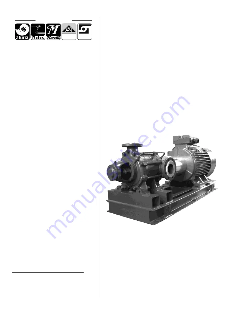
Summary of Contents for TK

Page 1: ...E EN NT TR RI IF FU UG GA AL L P PU UM MP PS S I IN NS ST TR RU UC CT TI IO ON N M MA AN NU UA AL L 20060 Gessate MILANO ITALY Piazza Aturia 9 Tel 39 0295423200 Fax 39 0295423202 www gruppoaturia com Gruppo Aturia S p A Gruppo Aturia AUDOLI BERTOLA ARIS CHIAPPA ...

Page 2: ... CAP 4 INSTALLATION 4 1 Installation 4 2 Alignment 4 3 Electrical Connections CAP 5 COMMISSIONING AND STARTUP 5 1 Startup CAP 6 MAINTENANCE 6 1 Ordinary Maintenance 6 2 Pump stop CAP 7 PUMP DISASSEMBLY 7 1 Before disassembly 7 2 Pump disassembly CAP 8 REASSEMBLIG 8 1 Before reassembly CAP 9 SPARE PARTS CAP 10 FAULT FINDING CHART CAP 11 DECOMMISSIONING 10 1 Decommissioning and dismantlement ENCLOSE...

Page 3: ...MPROPER USE OF THE PUMP BY UNSKILLED PERSONNEL MAY RESULT IN HEAVY DAMAGE TO THINGS AND OR INJURIES TO THE PEOPLE ATURIA TECHNICAL ASSISTANCE IS READILY AVAILABLE FOR ANY PROBLEM PLEASE CONTACT US ALSO BY PHONE 2 SHIPPING DOCUMENTS CHECK Check the equipment at delivery against the accompanying documents paying paticular attention to its completeness and to possible damages occured during transport...

Page 4: ...ing feet on suction side are located under the first stage to allow different orientations of suction nozzle while for larger sizes they are located under the suction casing In this latter case orientation of suction nozzle should be specified by the customer at pump ordering Hydraulical balancing of each impeller guarantees full absorption of axial thrust The shaft is supported by sturdy grease l...

Page 5: ... at 1 meter from the pump and elaborated according to ISO curve A standard R 1680 MOTOR NOISE LEVELS Db A MOTOR NOISE LEVELS Db A SIZE 2 POLES 4 POLES SIZE 2 POLES 4 POLES 63 65 61 180L 83 71 71 67 62 200 83 71 80 71 64 225 88 74 90 73 66 250 88 74 100 77 68 280 89 83 112 79 69 315S 89 83 132 80 69 315M 90 84 160 81 69 355 91 87 180M 81 69 400 93 89 For other motors the table values shall be compa...

Page 6: ...ment fit for its weight and for the shape of its packing case see side pictures Hand lifting is allowed only for weights lower than 20 kilograms 2 2 Site installations During site installation and maintenance a safety transport of all components must be done The specialized personnel must use proper slings in order to avoid any damage to the pump and to the people The lifting eyebolts of pumping s...

Page 7: ...an by compressed air then dry carefully inside the pump if necessary Protect the pump inside with anti condensation products and close the flanges so that no foreign objects can enter the pump Cover the pump with a plastic film and put inside some products the prevent water condensation Check protections periodically It is recommended that the pump shaft is rotated at regular intervals every 30 da...

Page 8: ...heck for pump suitability installation safety and pump life 3 2 Precautions during operation Never put your hands or any kind of object into pump openings where the shaft rotates see side picture In case of gland packing pay attention when adjusting the gland as gland nuts are very close to the shaft If warm water is pumped do not touch the pump Protect motor and electric parts in general accordin...

Page 9: ... the pump by wrong handling Don t pressurize the pump beyond recommended limits Avoid dry running operation at lower capacity than allowed or running with closed gate valve at discharge Avoid cold fluids uneven contact with the warm surfaces of the pump Don t use the pump unproperly with dangerous fluids or different from what specified in the order data sheets 3 4 In case of emergency Switch off ...

Page 10: ...e on the pump delivery flange see side pictures PIPINGS We recommend to support adequately the pipings to avoid any kind of stress to the pump suction and delivery nozzles with resulting difficulties to proper pump operation Pipe dimensions should not be determined according to the pumps nozzles diameters but only according to friction losses Avoid narrow bends and elbows and conical joints wrongl...

Page 11: ...ignment can be checked more accurately by using a millesimal comparator millesimal dial indicator THE COUPLING GUARD MUST BE FITTED ON BASEPLATE AFTER ALIGNMENT 4 3 Electrical connections Electrical connections should be made only by specialized personnel strictly following the instructions of motor and electrical equipments manufacturers In case of three phase line make sure that voltage is the s...

Page 12: ...valve slowly but fully till reaching the required pressure shown on pressure gauge Avoid dry running During operation check shaft seal If a mechanical seal is installed there should be no leaks with gland packing there should be a continuous dropping to ensure lubrication between packing and shaft sleeve Check also that the pump runs within its operating limits and that voltage rates reported on c...

Page 13: ...eplace all the packing and not only those at the ends To replace the packing remove the gland and then the packing with a flexible extractor available by seals manufacturers Do not over tighten the packing as that will cause their immediate failure Check shaft sleeve it should be smooth also under the packing If the sleeve is scratched or shows any sign of surface roughness it should be machined a...

Page 14: ...unt of grease or a failed bearing If a danger of frost exists drain the pump completely during idle periods by unscrewing the draining plug see picture aside Fill then the pump again as described in sect 5 1 6 2 Pump stop Before any stop it is necessary to Switch off the line voltage Close suction and delivery gate valves Drain the pump through the hole on the lower side of the pump casing ...

Page 15: ...workshop or to the manufacturer 7 2 Pump disassembly ref dwg EKY0101 EKY0201 Start disassembly from delivery side removing the cover 3266 from the bearing housing 3200 after removing the relative fixing screws Unscrew the bearing nut 6586 and after loosening the bearing housing 3200 remove it complete with radial ball bearing 3011 strike it on the sides using a lead hammer Remove the shaft 2110 th...

Page 16: ...icated in the following table CLEARANCE REFERENCE MINIMUM DIAMETER DIAMETER CLEARANCE 50 mm 0 25mm from 50 65 0 28mm from 65 80 0 30mm from 80 90 0 33mm from 90 100 0 35mm from 100 115 0 38mm from 115 125 0 40mm from 125 150 0 43mm from 150 175 0 45mm from 175 200 0 48mm from 200 225 0 50mm from 225 250 0 53mm from 250 275 0 55mm During operation this clearance is bound to rise with consequent per...

Page 17: ...132 2 impeller 82200 diffuser 1413 key 6710 2 spacer sleeve 2461 and stage casing 1150 with the proper O ring 4610 Go on in this way up to the discharge casing 1140 and remember to insert the bush 4132 1 Insert the shaft sleeve 2450 2 the spacer sleeve 2461 2 and let the gland 4120 slide on the axis Close the pump with the proper tie bolt 6571 reassembly the bearing housing 3200 where the bearing ...

Page 18: ...ocessing of Your order when ordering spare parts please specify Pump type Pump serial number Part name and number as listed on sectional drawing Pump type and serial number are printed on the nameplate For recommended spare parts see part list EKY0102 EKY0103 EKY0202 EKY0203 ...

Page 19: ... to the duty required 2 2 1 Foreign bodies at impeller channels or the same causes as points 1 1 1 3 1 5 1 6 1 7 Clean impeller channels See mentioned points and suggested remedies UNSUFFICIENT DELIVERY 2 2 Undersized suction pipe or foot valve or wrong positioning of suction pipe Correct installation 2 3 Worn impeller and or pump casing Replace impeller Repair pump casing see section 8 3 3 1 Liqu...

Page 20: ... position Repair the pump see section 8 6 6 1 Unbalanced rotating assembly Repair the pump see chapter 8 THE PUMP VIBRATES AND IT IS NOISY 6 2 Worn pump bearings See chapter 8 6 3 The pump runs with too low or too high capacity also the same causes as points 1 5 2 1 2 2 Operate the pump differently remove the causes of the malfunctioning ...

Page 21: ... 30 54 TK65 100 SUCTION 90 100 80 160 50 36 41 74 DELIVERY 55 50 60 95 40 29 33 58 TK80 125 SUCTION 110 125 100 200 60 44 50 88 DELIVERY 70 60 75 120 44 32 36 65 TK100 150 SUCTION 135 150 120 240 75 53 62 110 DELIVERY 90 80 100 160 50 36 41 74 TK125 150 SUCTION 135 150 120 240 75 53 62 110 DELIVERY 110 100 125 200 60 44 50 88 TK150 200 SUCTION 150 175 140 280 80 62 70 130 DELIVERY 135 120 150 240 ...

Page 22: ...ng it should be properly disposed of It is important to make sure that no residual polluting liquids are trapped within the pump The materials used in pump construction are Steel and cast iron Aluminium Rubber and plastic Copper and brass The disposal of polluting liquids and materials should follow current environment regulations Environments protection is an increasingly pressing problem ...

Page 23: ......

Page 24: ...LTK0E01B 01 2012 23 ...

Page 25: ...LTK0E01B 01 2012 24 ...

Page 26: ...LTK0E01B 01 2012 25 ...

Page 27: ......

Page 28: ...LTK0E01B 01 2012 26 ...

Page 29: ...LTK0E01B 01 2012 27 ...

Page 30: ...LTK0E01B 01 2012 28 ...

Page 31: ...AZIONE Section 3 Declaration Noi Gruppo Aturia S p a Piazza Aturia 9 Gessate Mi dichiariamo che é garantita la conformità ai requisiti essenziali di sicurezza e di tutela della salute della Direttiva Macchine 2006 42 CE We Gruppo Aturia S p a Piazza Aturia 9 Gessate Mi declare that is in conformity with all the essential health and safety requirements of the Machinery Directive 2006 42 CE RESPONSA...

Page 32: ......

Reviews: