


POWER
S
TATU
S
S
1
S
2
E-BM-A
S
11
OVERALL DIMENSIONS [mm]
1 2 3 4
C
D
B
A
A, B, C, D connectors included
overall dimension with
assembled connectors
DIN rail
dimensions
11/19
12
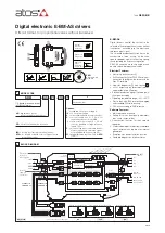
INSTALLATION
1.
To wire cables in the connectors:
1. press the button with a screwdriver
2. insert the cable termination
To unlock the driver from the DIN rail:
1. pull down the locking slide with a screwdriver
2. rotate up the driver
Note:
max conductor size: 2,5 mm
2
A
1
COIL S1
2
3
COIL S2
4
V+
1
D
V0
2
ENABLE
3
STATUS
4
DI1
1
C
DI2
2
DI3
3
DI4
4
B
1
CMD1
2
CMD-
3
CMD2
4
DGND
113.6
99
25
(*)
25
(*)
35
7.5
22.6
118.3
(*)
Space to remove the connectors
2.
1.
2.
10
DIAGNOSTIC LEDS
Four leds show driver operative conditions for immediate basic diagnostics. Please refer to the driver user manual for detailed information.
LED
COLOR
FUNCTION
FLASH RATE
DESCRIPTION
L1
GREEN
POWER
OFF
Power supply OFF
ON
Power supply ON
L2
GREEN
STATUS
OFF or ON
Fault conditions
Slow blinking
Driver disabled
Fast blinking
Driver enabled
L3 and L4
YELLOW
S1 and S2
OFF
PWM command OFF
ON
PWM command ON
Slow blinking
Coil not connected
Fast blinking
Short circuit on the solenoid
POWER
STATUS
S1
S2
L1
L2
L
3
L4