


G030
RJ45 CONNECTOR
PIN
SIGNAL
DESCRIPTION
1
/
Not connected
2
/
Not connected
3
/
Not connected
4
GND
Signal zero data line
5
RX
Driver receiving data line
6
TX
Driver transmitting data line
7
/
Not connected
8
/
Not connected
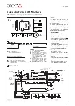
E-BM-A
S
POWER
STATUS
S1
S2
1
2
3
4
5
6
7
8
9
RJ45 CONNECTOR
RJ45 connector
(IEC 60603 standard)
for RS232 serial communication
8
CONNECTIONS
CONNECTOR
PIN
SIGNAL
TECHNICAL SPECIFICATIONS
NOTES
A
A1
SOL S1
Current to solenoid S1
Output - power PWM
A2
A3
SOL S2
Current to solenoid S2 (only for 05H version)
A4
B
B1
CMD1
Reference analog input: ±10 V
DC
/ ± 20 mA maximum range software selectable (see 4.2)
Input - analog signal
B2
CMD-
Standard
/P option
(see 4.4)
Zero signal, ground for reference signals
Reference for ±5 V
DC
output (AGND)
B3
CMD2
(1)
Reference analog input: ±10 V
DC
/ ± 20 mA maximum range software selectable (see 4.2)
B4
DGND
Optical insulated ground for on/off inputs (DI1 ÷ DI4)
C
Standard
/P option
(see 4.4)
Standard
Option /P
C1
DI1
Optical insulated on/off input 0 ÷ 24 V
DC
referred to pin B4 DGND (see 4.7)
For analog driver compatibility see section
5
Optical insulated on/off input 0 ÷ 24 V
DC
referred to pin B4 DGND (see 4.7)
For analog driver compatibility see section
5
Input - on/off signal
C2
DI2
C3
DI3
+5 V
DC
@ 10 mA output supply to pin B2 (AGND)
Input -
on/off
Output -
reference
analog
C4
DI4
-5 V
DC
@ 10 mA output supply to pin B2 (AGND)
D
D1
V+
Power supply 24 V
DC
(see 4.1)
Input - power supply
D2
V0
Power supply 0 V
DC
D3
ENABLE
Enable (24 V
DC
) or disable (0 V
DC
) the driver (see 4.5)
Input - on/off signal
D4
STATUS
Fault (default) or software selected output (see 4.6)
Output - on/off signal
The 4 fast plug-in connectors (A,B,C,D), included in the supply, provide simple wirings, easy driver’s replacement and the possibility to test the
signals directly on the connectors.
(1)
Only for 05H version, when used to drive two single solenoid valves or transducer input for /W option
WARNING:
if CMD2 is not used has to be connect to CMD- (ground)
Q
Q
1
p
1
p
pressure
feedback
reference signal
for valve regulation
7.7 - Hydraulic Power Limitation
Regulation curve
with and
without power limitation.
p1 x Q1 = max power limit
7.7 Hydraulic Power Limitation
(
/W option
, only for drivers E-BM-AS-PS-05H)
E-BM-AS drivers with /W option electronically perform hydraulic power limitation on:
- direct and pilot operated flow control valves
- direct and pilot operated directional control mechanical pressure compensator
- variable displacement pumps with proportional flow regulator
(e.g. PVPC-*-LQZ, tech. table A170)
The driver receives the flow reference signal by the analog external input CMD1 (see 4.2) or
by the internal generator (see 7.6) and a pressure transducer, installed in the hydraulic
system, has to be connected to the driver’s analog input CMD2.
When the actual requested hydraulic power
p
x
Q
(CMD2xCMD1) reaches the max power
limit (p1xQ1), internally set by software, the driver automatically reduces the flow regulation
of the valve. The higher is the pressure feedback the lower is the valve’s regulated flow:
Flow regulation = Min (
PowerLimit [sw setting]
; Flow Reference [CMD1])
Transducer Pressure [CMD2]