


7.4 Dither
The dither is an high frequency modulation of the current supplied to the solenoid, to reduce the
hysteresis of the valve’s regulation: a small vibration in the valve’s regulating parts considerably
reduces static friction effects.
Dither frequency can be set in a range from 80 to 500 Hz (default value is 200Hz).
Lower dither setting reduces the hysteresis but also reduces the regulation stability. In some
application this can lead to vibration and noise: right setting usually depends on system setup.
Default dither is a valid setting for a wide range of hydraulic applications
Scale B
Scale A
current
reference
Bias B
Bias A
t
t
t
DI4
DI3
DI2
DI1
t
reference
reference
current
Solenoid S1
Solenoid S2
7.5 - Linearization
7.4 - Dither
7.6 - Internal Reference Generation
Single internal generator selection (standard mode)
DI1
DI2
DI3
DI4
Reference
OFF
OFF
OFF
OFF
External
ON
OFF
OFF
OFF
Generation 1
(*)
ON
OFF
OFF
Generation 2
(*)
(*)
ON
OFF
Generation 3
(*)
(*)
(*)
ON
Generation 4
Double internal generator selection (standard mode)
DI1
DI2
S1
DI3
DI4
S2
OFF
OFF
External
OFF
OFF
External
ON
OFF
Generation 1
ON
OFF
Generation 1
(*)
ON
Generation 2
(*)
ON
Generation 2
(*) don’t care
7.5 Linearization
Linearization function allows to set the relation between the reference input signal and the
current supplied to the solenoid.
Linearization is useful for applications where it is required to linearize the valve’s regulation in
a defined working condition (e.g. maximum pressure control at defined working flow)
7.6 Internal Reference Generation
Internal generation of reference values is software selectable.
In this mode the 4 digital inputs of the driver (DI1..DI4) allow to activate the desired internal
reference signal, among the different driver’s stored values: external control unit can thus
manage complex machine profile by simple switching the reference signal, by 4 digital
inputs (see 4.7).
The digital inputs are software configurable into 2 different reference selection mode:
•
Standard mode
each digital input corresponds to a different value; up to 4 different internal values are
available (2+2 with E-BM-AS-PS-05H driving two single solenoid valves)
•
Binary mode
each digital input combination corresponds to a different value; up to 15 different internal
values are available (3+3 with E-BM-AS-PS-05H when driving two single solenoid valves)
A dedicated ramp time value can be set by software for each available stored reference
value.
Note: with all input signals (DI) set to zero, the driver can be commanded by external analog
reference also if internal reference generation is selected (for more information please refer
to the programming manual E-MAN-BM-AS).
7
MAIN SOFTWARE PARAMETER SETTINGS
current
reference
Bias A
Scale A
Bias B
Scale B
Solenoid S1
regulation
Solenoid S2
regulation
Bias A
Bias B
Threshold
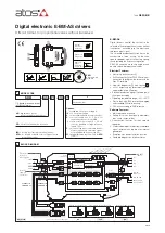
7.1, 7.2 - Scale, Bias & Threshold
The following is a brief description of the main settings and features of digital drivers. For a detailed descriptions of available settings, wirings
and installation procedures, please refer to the user manual included in the E-SW programming software:
E-MAN-BM-AS
- user manual for
E-BM-AS
7.1 Scale
Scale function allows to set the maximum current supplied to the solenoid, corresponding to the
max valve regulation, at maximum reference signal value.
This regulation allows to adapt the maximum current supplied from the driver to the specific
nominal current of the proportional valves to which the driver is coupled; it is also useful to redu-
ce the maximum valve regulation in front of maximum reference signal.
For double solenoid valves two different Scale regulations are available:
ScaleA for positive reference signal and ScaleB for negative reference signal
7.3 - Ramps
t
t
reference
current
7.3 Ramps
The ramp generator allows to convert sudden change of electronic reference signal into smooth
time-dependent increasing/decreasing of the current supplied to the solenoid.
Different ramp mode can be set:
- single ramp for any reference variation
- two ramps for increasing and for decreasing reference variations
- four ramps for positive/negative signal values and increasing/decreasing reference variations
Ramp generator is useful for application where smooth hydraulic actuation is necessary to avoid
machine vibration and shocks.
If the proportional valve is driven by a closed loop controller, the ramps can lead to unstable
behaviour, for these applications ramp function can be software disabled (default setting)
7.2 Bias and Threshold
Proportional valves may be provided with a dead band in the hydraulic regulation correspon-
ding to their switch-off status.
This dead band discontinuity in the valve’s regulation can be compensated by activating the
Bias function, which adds a fixed preset Bias value to the reference signal (external input or
internally generated).
The Bias function is activated when the reference signal overcome the Threshold value, preset
into the driver.
The Bias setting allows to calibrate the Bias current supplied to the solenoid of the specific pro-
portional valve to which the driver is coupled.
The Threshold setting is useful to avoid undesired valve regulation at zero reference signal when
electric noise is present on the analog input signal: smaller threshold reduces the reference
signal dead band, greater values are less affected by electric noise presence.
If internal reference generation is active (see 7.6), threshold should be set to 0.
For double solenoid valves two different Bias regulations are available: positive reference signal
activates BiasA for solenoid S1 and negative reference signal activates BiasB for solenoid S2