

Atop Technologies, Inc.
Wireless Client Adaptor
EW5300
Quick Start Guide
Version 1.1
Updated on Sept. 14, 2010
Overview
The EW5300 have one Ethernet port to connect to IEEE
802.11 b/g wireless network. It is ideal to create a
“bridge” for an Ethernet device that has an Ethernet
interface to a wireless network. By using EW5300, these
devices can be communicated over a wireless network
to send or receive the information from, e.g., a backend
server or database. This document intends to provide
customers with brief descriptions about the product and
to assist customers to get started. For detailed
information and operations of the product, please refer
to the product user’s manual in the Product CD.
Packaging Included
Atop EW5300 Wireless Client Adaptor
3-Pin Terminal Block for Power Connector
(TB model only)
4
dBi
Antenna
Atop EW5300 Quick Start Guide with Product
Warranty Card
Product CD (User’s Manual and Utility Software)
Wall mount kits x 2 (optional)
Hardware Setup
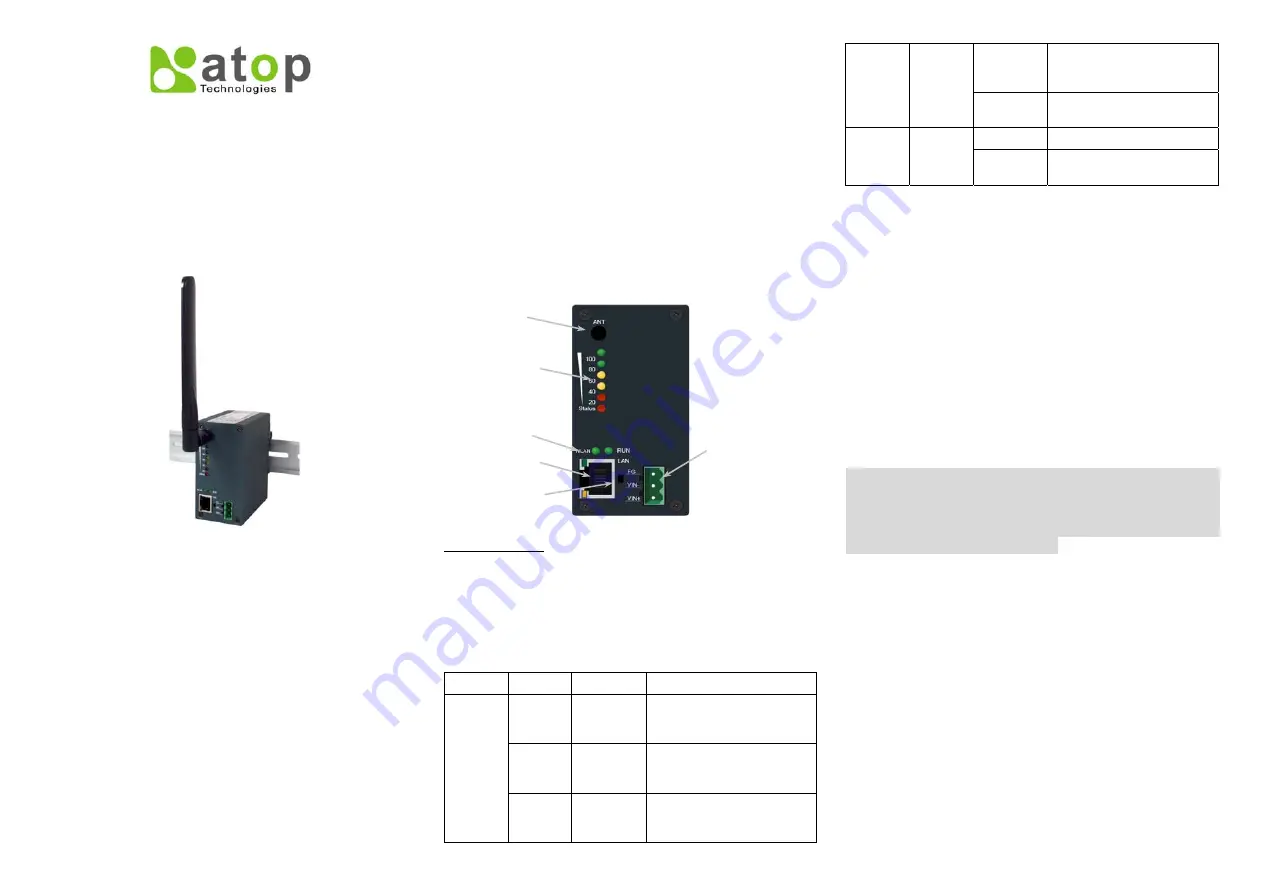
The following figure shows the components on the panel
of EW5300.
*Reset Button
: Press Reset button continuously over
sec to reload the device to the factory default settings.
3
LED Indications
The LEDs indicate the status of
EW5300
. Please see
the front panel
Name
Color
Status
Description
Red*2
ON
Its strength is poor, but the
link is connected for the
wireless link
Yellow*2
ON
Its strength is good, the
wireless link can supply a
good transfer channel
Signal
Strength
Green*2
ON
Its strength is very excellent
and the link is connected on
best status
Off
Wireless Link is Broken or
No data transmit or receive
via wireless connectivity
WLAN
Green
Blink
Wireless Traffic be indicted
for data transfer
OFF/ON
System is not ready or halt
RUN
Green
Blink
System is running and LED
is blink per 0.5 sec
Hardware Installation
Step 1: Connect the device with the antenna and to a
LAN switch with a standard UTP/STP cable.
Step 2: Attach the power wire to the device for 9~48V
DC, and confirm the power polarity carefully.
Please check the Terminal Block diagram for
power supply to connect the device to a power
supply.
Step 3: Wait for the device to start up after 60 seconds,
and see the next section for network
configuration
UL Notice for Power supplier
EW5300 series products are intended to be supplied by
a Listed Power Unit marked with “LPS”, “Limited Power
Source” or “Class 2” and output rate 9~48VDC, 1A
minimum. Otherwise, use the recommended power
supply in “Optional Accessories.
Network Configuration
There are two steps to configure the device. First, you
need to find the device in your network using our
software tool, Deviceview. Once the device is properly
configured with a new IP address; you can further
configure the device’s wireless network interface using a
web browser or a telnet terminal.
Configure using Deviceview software
Use
Deviceview
that comes with Product CD
to
configure the network parameters of EW5300. Please
refer to
Appendix A Deviceview Configuration Utility
in the product user’s manual for more details.
Terminal
Block for DC
Power
Antenna
Connector
Wireless
Status LEDs
System/WLAN
Status LED
Reset
10/100M
Ethernet