


Industrial Managed
Ethernet Switch – EH9711
User Manual
Page
163
of
223
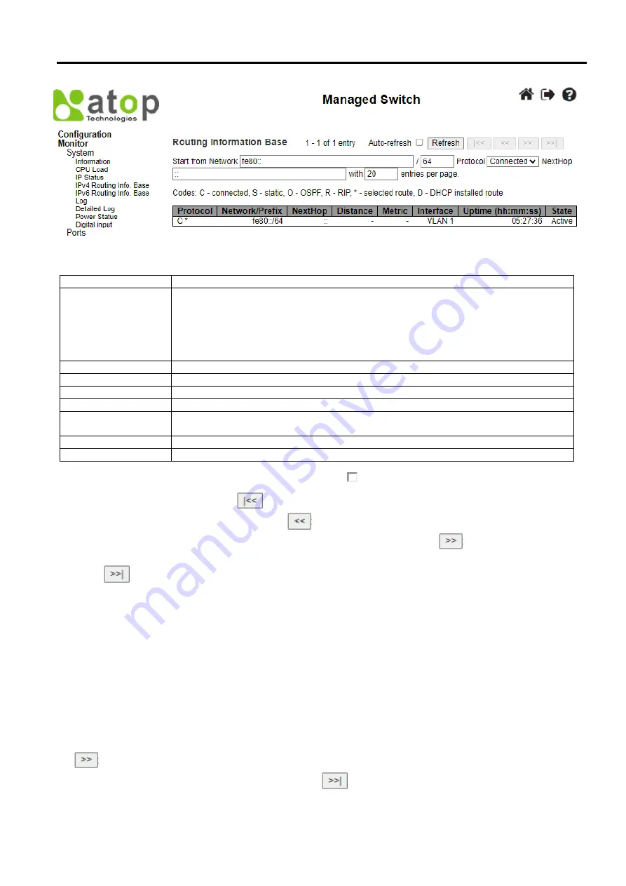
Figure 3.6 Webpage to Monitor System’s IPv6 Routing Information Base
Table 3.4 Monitoring Descriptions of System’s IPv6 Routing Information Base
Label
Description
Protocol
The protocol that installed this route.
DHCP
: The route is created by DHCP.
Connected
: The destination network is connected directly.
Static
: The route is created by user.
OSPF
: The route is created by OSPF.
RIP
: The route is created by RIP.
Network/Prefix
Network and prefix (example 10.0.0.0/16) of the given route entry.
NextHop
Next-hop IP address. All-zeroes indicates the link is directly connected.
Distance
Distance of the route.
Metric
Metric of the route.
Interface
If the next-hop address is a link-local address, then this is the VLAN interface of the link-
local address. Otherwise, this value is not used
Uptime (hh:ss:mm)
Time (in seconds) since this route was created
State
Destination is active.
Click
Refresh button
to refresh the page immediately. Auto-refresh
: Check this box to refresh the page automatically.
Automatic refresh occurs every 3 seconds.
: Updates the table entries, starting from the first available entry. If the first
entry of the table is displayed, the button is disabled.
: Updates the table entries, ending at the entry prior to the first
entry currently displayed. If the first entry of the table is displayed, the button is disabled.
: Updates the table entries,
starting from the entry next to the last entry currently displayed. If the last entry of the table is displayed, the button is
disabled.
: Updates the table entries, ending at the last available entry. If the last entry of the table is displayed, the
button is disabled.
3.1.6
Log
The managed switch’s system log information is provided in this
Log
webpage shown in Figure 3.7. Each page can display
up to 999 table entries which can be selected through the "
entries per page
" input field. When first visited, the web page will
show the beginning entries of this table. The "
Level
" input field is used to filter the display system log entries. The "
Clear
Level
" input field is used to specify which system log entries will be cleared. To clear specific system log entries, select the
clear level first then click the
Clear
button.
The "
Start from ID
" input field allows the user to change the starting point in this table. Clicking
the Refresh
button will
update the displayed table starting from that or the closest next entry match. In addition, these input fields will upon
a
Refresh
button click - assume the value of the first displayed entry, allowing for continuous refresh with the same start
input field.
The
will use the last entry of the currently displayed table as a basis for the next lookup. When the end is reached the
text "No more entries" is shown in the displayed table. Use the
button to start over.


